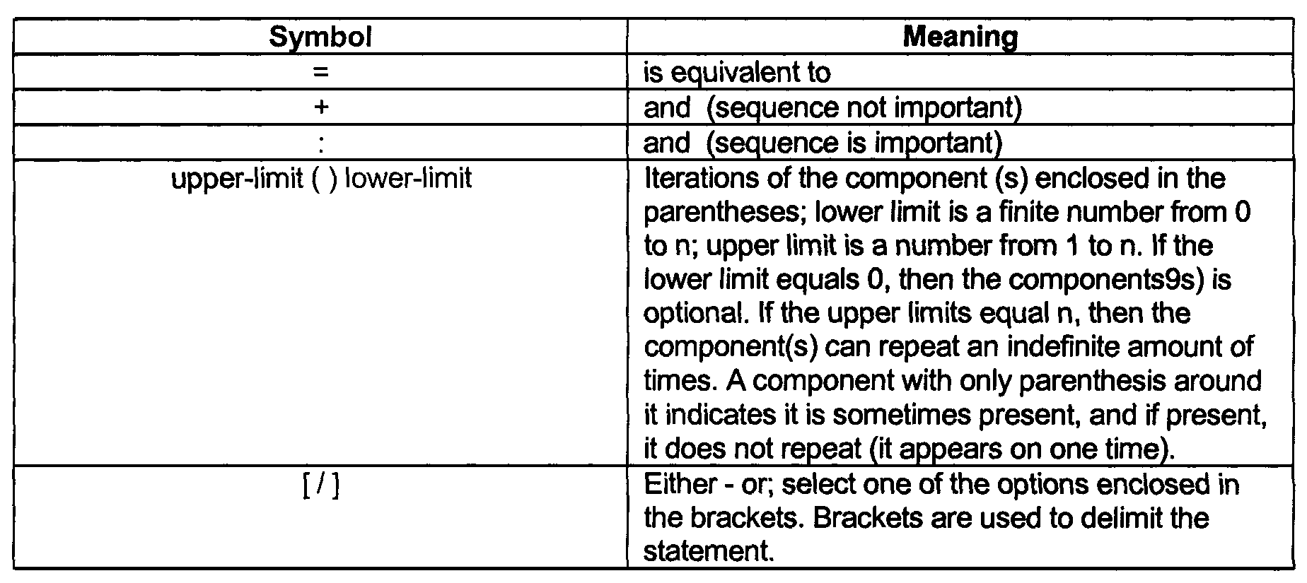
)
或 https:// 表示您已安全连接到 .gov 网站。仅在官方、安全的网站上共享敏感信息。
)
或 https:// 表示您已安全连接到 .gov 网站。仅在官方、安全的网站上共享敏感信息。
- 2.5.11 Analysis Techniques and Deliverables
- 2.5.11.1 Program Scope and Objectives
- 2.5.11.1.1 Background
- 2.5.11.1.2 Authority
- 2.5.11.1.3 Roles and Responsibilities
- 2.5.11.1.4 Program Management and Review
- 2.5.11.1.5 Program Controls
- 2.5.11.1.6 Terms and Acronyms
- 2.5.11.1.7 Related Resources
- 2.5.11.2 Model-Driven Architecture
- 2.5.11.3 Structured Analysis Overview
- 2.5.11.4 Structured Analysis Tools
- 2.5.11.4.1 Data Dictionary/Data Definition Matrix
- 2.5.11.4.2 Data Flow Diagrams
- 2.5.11.4.2.1 IRS Business Process Model and Notation (BPMN) Overview
- 2.5.11.4.2.2 Developing Data Flow Diagrams (DFDs)
- 2.5.11.4.2.2.1 Identifying a Data Flow Diagram
- 2.5.11.4.2.2.2 Naming a Data Flow Diagram
- 2.5.11.4.2.2.3 Numbering a Data Flow Diagram
- 2.5.11.4.2.2.4 Balancing Data Flow Diagrams
- 2.5.11.4.2.2.5 Types of Data Flow Diagrams
- 2.5.11.4.2.2.5.1 Current Physical Data Flow Diagram
- 2.5.11.4.2.2.5.2 Current Logical Data Flow Diagram
- 2.5.11.4.2.2.5.3 New Logical Data Flow Diagram
- 2.5.11.4.2.2.5.4 Depicting Files on Logical Data Flow Diagrams
- 2.5.11.4.2.2.5.5 New Physical Data Flow Diagram
- 2.5.11.4.2.2.5.6 Depicting Files on Physical Data Flow Diagrams
- 2.5.11.4.2.3 Leveling Data Flow Diagrams
- 2.5.11.4.2.4 Parent/Child Process Relationships
- 2.5.11.4.2.5 Leveling Conventions/Standards
- 2.5.11.4.2.6 Elements of a Data Flow Diagram (DFD) Overview
- 2.5.11.4.2.6.1 Data Stream
- 2.5.11.4.2.6.1.1 Naming Data Streams/Modifiers
- 2.5.11.4.2.6.1.2 Routers and Collectors
- 2.5.11.4.2.6.1.3 Split Data Stream
- 2.5.11.4.2.6.2 Process
- 2.5.11.4.2.6.1 Data Stream
- 2.5.11.4.2.7 Data Store
- 2.5.11.4.2.7.1 Accessing/Updating a Data Store
- 2.5.11.4.2.7.2 Updating Re-circulating Data Stores
- 2.5.11.4.2.8 Access Key
- 2.5.11.4.2.9 Source/Sink
- 2.5.11.4.2.10 Data Sorts
- 2.5.11.4.2.11 Off-Page Connector
- 2.5.11.4.2.12 Developing Data Definitions
- 2.5.11.4.2.12.1 Types of Data Definitions
- 2.5.11.4.2.12.2 Components of Data Definitions
- 2.5.11.4.2.12.3 Attributes and Cross-References
- 2.5.11.4.2.12.4 Data Streams/Elements
- 2.5.11.4.2.12.4.1 Naming Data Streams/Modifiers
- 2.5.11.4.2.12.5 Data Streams/Groups
- 2.5.11.4.2.12.6 Data Stores
- 2.5.11.4.2.12.7 External Entities
- 2.5.11.4.2.12.8 Avoiding Redundant Data Definitions
- 2.5.11.4.2.12.9 Defining the Contents of Data
- 2.5.11.4.2.12.10 Data Name Aliases
- 2.5.11.4.2.12.11 Approved Aliases
- 2.5.11.4.3 Transition to Design
- 2.5.11.4.3.1 Partitioning the Data Flow Diagrams
- 2.5.11.4.3.2 Packaging the Data Flow Diagrams
- 2.5.11.5 Developing Process Specifications
- 2.5.11.5.1 Process Specification Attributes
- 2.5.11.5.2 Type of Process Specifications
- 2.5.11.5.2.1 Primitive Level Process Specifications (mini specs)
- 2.5.11.5.2.2 Higher Level Process Specifications
- 2.5.11.5.3 General Rules for Writing Process Specifications
- 2.5.11.5.4 Structured English for Programming Languages Overview
- 2.5.11.5.4.1 Structured English for Programming Languages Vocabulary
- 2.5.11.5.4.2 Logical Constructs of Structured English
- 2.5.11.5.4.2.1 Sequence Construct
- 2.5.11.5.4.2.2 Decision Construct
- 2.5.11.5.4.2.3 Repetition Construct
- 2.5.11.5.5 Decision Tables
- 2.5.11.5.6 Decision Tree
- 2.5.11.5.7 Common Process Specifications
- 2.5.11.5.7.1 Attributes and Cross-References
- 2.5.11.5.7.2 Maintenance
- 2.5.11.5.8 Computer-Aided System Engineering (CASE) Tools
- 2.5.11.5.8.1 Advantages of the CASE Models
- 2.5.11.5.9 Joint Application Development (JAD) Methodology
- 2.5.11.5.10 Rapid Application Development (RAD) Methodology
- 2.5.11.5.10.1 IRS Prototyping/Visualization Overview
- 2.5.11.6 Functional Specification Package (FSP)
- 2.5.11.6.1 Data Flow Diagrams and Process Specifications
- 2.5.11.6.2 Data Definitions
- 2.5.11.6.3 Screen Displays
- 2.5.11.6.4 Reports/Layouts
- 2.5.11.6.5 Table of Contents/Cross References
- 2.5.11.7 Agile Model-Driven Architecture
- 2.5.11.7.1 IRS Agile Model-Driven Best Practices
- 2.5.11.8 Common Information Model (CIM) Management Schema
- 2.5.11.9 ≡ ≡ ≡ ≡ ≡ ≡ ≡ ≡ ≡ ≡ ≡ ≡ ≡ ≡ ≡ ≡ ≡ ≡ ≡ ≡ ≡ ≡ ≡ ≡ ≡ ≡ ≡ ≡ ≡
- 2.5.11.9.1 ≡ ≡ ≡ ≡ ≡ ≡ ≡ ≡ ≡ ≡ ≡ ≡ ≡ ≡ ≡ ≡ ≡ ≡ ≡ ≡ ≡ ≡ ≡ ≡ ≡ ≡ ≡ ≡ ≡ ≡ ≡
- 2.5.11.9.1.1 ≡ ≡ ≡ ≡ ≡ ≡ ≡ ≡ ≡ ≡ ≡ ≡ ≡ ≡ ≡ ≡ ≡ ≡ ≡ ≡ ≡ ≡ ≡ ≡ ≡
- 2.5.11.9.1.1.1 ≡ ≡ ≡ ≡ ≡ ≡ ≡ ≡ ≡ ≡ ≡ ≡ ≡ ≡ ≡ ≡ ≡ ≡ ≡ ≡ ≡ ≡ ≡ ≡ ≡ ≡ ≡ ≡ ≡ ≡ ≡
- 2.5.11.9.1.1.2 ≡ ≡ ≡ ≡ ≡ ≡ ≡ ≡ ≡ ≡ ≡ ≡ ≡ ≡ ≡ ≡ ≡ ≡ ≡ ≡ ≡ ≡ ≡ ≡
- 2.5.11.9.1.1.3 ≡ ≡ ≡ ≡ ≡ ≡ ≡ ≡ ≡ ≡ ≡ ≡ ≡ ≡ ≡ ≡ ≡ ≡ ≡ ≡ ≡ ≡ ≡ ≡ ≡
- 2.5.11.9.1.1.4 ≡ ≡ ≡ ≡ ≡ ≡ ≡ ≡ ≡ ≡ ≡ ≡ ≡ ≡ ≡ ≡ ≡ ≡ ≡ ≡ ≡ ≡ ≡ ≡ ≡ ≡ ≡ ≡ ≡ ≡ ≡ ≡
- 2.5.11.9.1.1 ≡ ≡ ≡ ≡ ≡ ≡ ≡ ≡ ≡ ≡ ≡ ≡ ≡ ≡ ≡ ≡ ≡ ≡ ≡ ≡ ≡ ≡ ≡ ≡ ≡
- 2.5.11.9.1 ≡ ≡ ≡ ≡ ≡ ≡ ≡ ≡ ≡ ≡ ≡ ≡ ≡ ≡ ≡ ≡ ≡ ≡ ≡ ≡ ≡ ≡ ≡ ≡ ≡ ≡ ≡ ≡ ≡ ≡ ≡
- Exhibit 2.5.11-1 Format for a Leveled Data Flow Diagram
- Exhibit 2.5.11-2 Symbols Used to Define Data
- Exhibit 2.5.11-3 A Procedure described using a Narration, then using a Decision Table
- Exhibit 2.5.11-4 Common Process Specification Example
- Exhibit 2.5.11-5 Acronyms/Terms
- Exhibit 2.5.11-6 Terms/Definitions
- Exhibit 2.5.11-7 ≡ ≡ ≡ ≡ ≡ ≡ ≡ ≡ ≡ ≡ ≡ ≡ ≡ ≡ ≡ ≡ ≡ ≡ ≡ ≡ ≡ ≡ ≡ ≡ ≡
- 2.5.11.1 Program Scope and Objectives
Part 2. Information Technology
Chapter 5. Systems Development
Section 11. Analysis Techniques and Deliverables
2.5.11 Analysis Techniques and Deliverables
Manual Transmittal
November 22, 2023
Purpose
(1) This transmits revised Internal Revenue Manual (IRM) 2.5.11, System Development, Analysis Techniques and Deliverables.
Background
This IRM 2.5.11 authorizes system development standards and analysis techniques such as structured analysis, Agile and other IRS approved techniques that involves analysis, description, specification, and decomposition of business processes and data to derive a result. These system development techniques apply to all IRS IT government employees and contractual workers. This manual was developed to establish analysis techniques and deliverable descriptions for system development.
Material Changes
(1) Changed Chief Information Officer from, Nancy A. Sieger to Kaschit Pandya Acting Chief Information Officer for the signature.
(2) Background, Removed the sentence “This IRM 2.5.11 authorizes the standards, techniques, and other controls for Structured Analysis and Structure Design”. Since this IRM is also for agile methodology the statement was not correct.
(3) IRM 2.5.11.1.3 (1) Changed Federal Information Security "Management " Act to Federal Information Security "Modernization" Act because it was incorrect.
(4) IRM 2.5.11.1.3 (3), Changed Facilities Management & Security Services (FMSS) to Agency-Wide Shared Services per guidance IRM 1.1.17
(5) IRM 2.5.11.1.6, Changed the title from Terms/Acronyms/Definitions to Terms and Definitions
(6) IRM 2.5.11.4.2.2.4, changed the Figure to correct Figure numbers.
(7) IRM 2.5.11.4.2.2.5.3 (1), changed the sentence from "To accommodate required changes to a system, reexamine the rationale behind the why and the way processes are done. Modify the depiction, processes, and data stores to visualize the model’s new state to be considered and implemented. " to "To accommodate required changes to a system, reexamine the rationale behind the why and the way processes are done. Modify the depiction, processes, and data stores to visualize the model’s new state to be considered and implemented" .
(8) IRM 2.5.11.7, Added Agile Model-Driven Architecture.
(9) IRM 2.5.11.7 (10), Removed the Requirements Engineering Process Office link because it was not secure, this link was initially redacted.
(10) IRM 2.5.11.7 (11), Removed the Enterprise Data Management Office link because it was not secure, this link was initially redacted.
(11) IRM 2.5.11.8, Added Common Information Model (CIM) Management Schema.
(12) IRM 2.5.11.8.1, Added Common Information Model (CIM) Management Schema Types.
(13) IRM 2.5.11.9 (4), Changed Figure 2.5.11-31 to correct 2.5.11-38
(14) IRM 2.5.11.9, Added IRS Power Platform Business Intelligence (BI) Guidance.
(15) IRM 2.5.11.8.1 (9) , Changed sentence to "Useful for when the data model contains many dimensions consisting of few attributes" .
(16) IRM 2.5.11.9.1 , Added Microsoft Power Platform Business Intelligence (BI) Best Practices.
(17) IRM 2.5.11.9.1 (1), Removed extra comma after subject-matter-experts.
(18) IRM 2.5.11.9.1.1 , Added Power Business Intelligence (BI) Dataflows.
(19) IRM 2.5.11.9.1.1.1, Added Power Business Intelligence (BI) Dataflows Best Practices.
(20) IRM 2.5.11.9.1.1.2, Added Power Business Intelligence (BI) Architecture.
(21) IRM 2.5.11.9.1.1.3 , Added IRS Best Practices for Power BI Dashboard Design.
(22) IRM 2.5.11.9.1.1.4 , Added IRS Power Business Intelligence (BI) Information Security.
(23) IRM 2.5.11.9.1.1.3, Added IRS Best Practices for Power BI Dashboard Design.
(24) IRM 2.5.11.9.1.1.3 (4) c In the first sentence update the word "importance" to "important".
(25) IRM 2.5.11.4.2.12.2, Changed the table format from 6.5″ to 4.5″
(26) IRM 2.5.11.4.2.12.4, Removed the underline as it is not consistently used throughout the IRM.
(27) Throughout this IRM, Changed "Agency" to "IRS"
(28) Figure 2.5.11-31, Common Information Model (CIM) Example 1
(29) Figure 2.5.11-32, CIM Example 2
(30) Figure 2.5.11-33, Table Describing Power BI Suite of Tools
(31) Figure 2.5.11-34, Depiction of Components in the Power BI Personal (Self-Service)
(32) Figure 2.5.11-35, Diagram of Small Team Collaboration in Power BI Service
(33) Figure 2.5.11-36, Table Describing Power BI Architecture
(34) Figure 2.5.11-37, Table Describing Power BI Data Types
(35) Exhibit 2.5.11-5, Acronyms/Terms, Added:
-
ASQ - Application Standards and Quality
-
CIM - Common Information Model
-
ISS - Integrated Solutions Section
(36) Exhibit 2.5.11-7, Added IRS Power Business Intelligence (BI) Example Report
Effect on Other Documents
This IRM supersedes IRM 2.5.11 dated 12-13-2021, and supplements IRM 2.5.1 System Development.Audience
The audience intended for this transmittal applies to all engineering, development, and maintenance provided by IRS personnel and contractors for IRS systems in the Enterprise Architecture . This IRM applies to all engineering, development, and maintenance IRS personnel including contractors.Effective Date
(11-22-2023)
Kaschit Pandya
Acting, Chief Information Officer
-
Scope: The guidelines, standards, techniques, and other controls established in this manual apply to all software developed for the Internal Revenue Service. This development includes work performed by government employees as well as contractors. For system development purposes, the controls established in this manual may be used with any IRS approved life cycle, e.g., Software Development Life Cycle (SDLC) and/or Enterprise Architecture (EA), and One Solution Development Lifecycle (OneSDLC) which replaced Enterprise Lifecycle (ELC).
-
Purpose: This manual describes systems analysis techniques that provide a systematic and broader expectation to understanding, examining and creating or modifying the system to meet specific objectives. System analysis and design is an interactive and creative process techniques for modeling processes/data flows among these processes, defining data, and specifying processes. This manual is distributed to promote the development of business models that are easy to understand, change, and maintain.
-
Audience: This manual applies to Information Technology (IT) managers and personnel responsible for engineering, developing, or maintaining IRS software systems identified in the Enterprise Architecture. This engineering, development, and maintenance include that performed by government employees as well as contractors.
-
Policy Owner: The Chief Information Officer is the authority for this IRM.
-
Program Owner: The Information Technology, Application Development (AD) Director of Technical Integration Office is responsible for the administration, procedures, and updates related to the program.
-
Primary Stakeholders: The software developers and business owners of Internal Revenue Service are stakeholders for the guidelines, standards, techniques, and other controls established in this manual.
-
Program Goals: To provide an analysis of IRS systems that assist management in evaluating or defining the resource requirements in terms of hardware and software. Hence, if any additional resources are required, this would suggest an investment and return on investment (ROI)..Implementing system development analysis helps with authenticating the feasibility from all aspects if the technical, economical and operational needs are possible.
-
This IRM authorizes system development analysis techniques such as structured analysis, Agile and other IRS approved techniques that involves analysis, description, specification, and decomposition of business processes and data to derive a result that is: graphic and concise, non-redundant, top-down partitioned, and logical instead of physical. This technique uses logical models to enhance communication by emphasizing what (logically) needs to be designed, and not how (physically) to design it.
-
Data flow diagrams, data definitions, and process specifications are the tools used in structured analysis. The primary deliverable that results from applying structured analysis is the functional specification package. This deliverable comprises of data flow diagrams, data definitions, and process specifications.
-
IRM 2.5.1 System Development, is the overarching IRM for all System Development programs within the IRS
-
IRM 10.5.1 Security, Privacy and Assurance, Privacy, and Information Protection, Privacy Policy
-
IRM 10.8.6 Security, Privacy and Assurance, Information Technology (IT) Security, Application Security and Development
-
Clinger-Cohen Act of 1996
-
Federal Information Security Modernization Act of 2014, FISMA 2014
-
The Office of Management and Budget (OMB)
-
Government Performance Results Act, 1993
-
Treasury Inspector General Tax Administration (TIGTA)
-
Information Technology (IT), Cybersecurity: Cybersecurity manages the IRS IT Security program in accordance with the Federal Information Security Modernization Act with the goal of delivering effective and professional customer service to business units and support functions within the IRS. These procedures are done as the following:
-
Provide valid risk mitigated solutions to security inquisitions.
-
Respond to incidents quickly and effectively to eliminate risks/threats.
-
Ensure all IT security policies and procedures are actively developed and updated.
-
Provide security advice to IRS constituents, and proactively monitor IRS robust security program for any required modifications or enhancements.
-
-
Director, Enterprise Operations (EOps), Data Management Services & Support (DMSS): Directs and oversees reliable database and storage operations by pioneering improvements in data services. Other responsibilities are as follows:
-
Plan, build, operate, and maintain the IRS’s data management technologies/processes.
-
Ensure level 2 and 3 support is administered to address customer database requirements.
-
-
Applications Development (AD): AD is responsible for building, testing, delivering, and maintaining integrated information applications systems, e.g., software solutions, to support modernized systems and production environment to achieve the mission and objectives of the Service. Additional, AD is responsible for the following:
• AD works in partnership with customers to improve the quality of and deliver changes to IRS information systems products and services.
• Establishes and maintains rigorous contract and fiscal management, oversight, quality assurance, and program risk management processes to ensure that strategic plans and priorities are being met.
• Design solutions for IRS accounting, financial, procurement and HR systems.
• Maintains the effectiveness and enhance the integration of IRS installed base production systems and infrastructure while modernizing core business systems and infrastructure.
• Ensure the posting of data to all master files.
• Provides quality assessment/assurance of deliverables and processes. Application Development’s (AD) chain of command and responsibilities include:-
Commissioner: Oversees and provides overall strategic direction for the IRS. The Commissioner’s and Deputy Commissioner’s focus is for the IRS’s services programs, enforcement, operations support, and organizations. Additionally, the Commissioner’s vision is enhancing services to the nation’s taxpayers, balancing appropriate enforcement of the nation’s tax laws while respecting taxpayers’ rights.
-
Deputy Commissioner, Operation Support (DCOS): Oversees the operations of Facilities Management & Security Services (FMSS): Chief Financial Officer, Human Capital Office, Information Technology, Planning Programming and Audit Oversight and Privacy, and Governmental Liaison and Disclosure.
-
Chief Information Officer (CIO): The CIO leads Information Technology, and advises the Commissioner on Information Technology matters, manages all IRS IT resources, and is responsible for delivering and maintaining modernized information systems throughout the IRS. Assisting the Chief Technology Officer (CTO) is the Deputy Chief Information Officer for Operations.
-
Application Development (AD) Associate Chief Information Officer (ACIO): The AD ACIO reports directly to the CIO; oversees and ensures the quality of: building, unit testing, delivering, and maintaining integrated enterprise-wide applications systems to support modernized and legacy systems in the production environment to achieve the mission of the Service. AD works in partnership with customers to improve the quality of and deliver changes to IRS information systems products and services.
-
Deputy AD Associate CIO (ACIO): The Deputy AD ACIO reports directly to the AD ACIO, and is responsible for:
• Leading strategic priorities to enable the AD Vision, IT Technology Roadmap and the IRS future state
• Executive planning and management of the development organization which ensures all filing season programs are developed, tested, and delivered on-time and within budget
-
-
AD has the following Domains:
• Compliance Domain
• Corporate Data Domain
• Customer Service Domain
• Data Delivery Service (DDS) Domain
• Delivery Management; Quality Assurance (DMQA) Domain
• Identity & Access Management (IAM) Organization Domain
• Internal Management Domain
• Submission Processing Domain
• Technical Integration Organization (TIO) Domain -
Director, Compliance: Provides executive direction for a wide suite of Compliance focused applications, and oversees the IT Software Development organization to ensure the quality of production ready applications. Directs and oversees a unified cross-divisional approach to compliance strategies needing collaboration pertaining to the following:
-
Abusive tax avoidance transactions needing a coordinated response
-
Cross-divisional technical issues
-
Emerging issues
-
Service-wide operational procedures
-
-
Director, AD Corporate Data: Directs and oversees the provisioning of authoritative databases, refund identification, notice generation, and reporting.
-
Director, Customer Service: Directs and oversees Customer Service Support for service and communication with internal and external customers and providing taxpayers with self-service online capabilities.
-
Customer Service Domain’s applications and systems provide:
• Tax law assistance
• Taxpayer education
• Access to taxpayer account data
• Maintenance of modernized information systems that meet the customer’s needs for researching, updating, analyzing, and managing taxpayer accounts -
Services to internal and external customers are provided through five primary means:
• Centralized Contact Centers (for telephone, written, and electronic inquiries)
• Self-service applications (via the telephone and Internet)
• Field Assistance (for walk-in assistance)
• Web Services
• Management of Taxpayer Accounts
-
-
Director, Data Delivery Services: Directs, oversees, and ensures the quality of data with repeatable processes in a scalable environment. The enterprise data strategy is to transform DDS into a data centric organization dedicated to deliver Data as a Service (DaaS) through:
-
Innovation - new methods and discoveries
-
Motivate - incent and enable individuals
-
Renovation - streamline or automate
-
-
Director, Delivery Management; Quality Assurance (DMQA): Executes the mission of DMQA by ensuring AD has a coordinated, cross-domain, and cross-organizational approach to delivering AD systems and software applications. Additionally, the DMQA Director reports to the AD ACIO, and chairs the AD Risk Review Board.
-
Director, Identity & Access Management (IAM): Provides oversight and direction for continual secure online interaction by verifying and establishing an individual's identity before providing access to taxpayer information “identity proofing”, while staying compliant within federal security requirements.
-
Director, Internal Management: Provides oversight for the builds, tests, deliveries, refund identification, notice generation, and reporting.
-
Director, Submission Processing: Provides oversight to an organization of over 17,000 employees comprised of: a headquarters staff responsible for developing program policies and procedures, and five Wage& Investment processing centers. Additionally, the Director, Submission Processing is responsible for processing over 500 million individual and business tax returns through both electronic and paper methods.
-
Director, Technical Integration: Provides strategic technical organization oversight ensuring applicable guidance, collaboration, consolidation of technical integration issues and quality assurance for the Applications Development portfolio.
-
Program Reports:
-
Model driven requirement document
-
Customer requirement
-
Business requirement decomposition
-
Business physical data flow diagram
-
Business logical data flow diagram
-
-
Program Effectiveness:
-
Using special conventions on Model Data Flows
-
Leveling Data Flow Diagrams
-
Identify and balancing Data Flow Diagrams
-
-
The Requirements Engineering Program Office of Business Planning and Risk Management (BPRM) is the IRS authority on providing standards and guidance to Requirements Engineering activities, process modeling, and requirements-related solutions.
-
This office oversees Requirements Development and Requirements Management efforts on all business change, software development, systems integration, and legacy system upgrades throughout IRS Information Technology.
-
For Terms and Acronyms, see Exhibit 2.5.11-5
-
For Terms and Definitions, see Exhibit 2.5.11-6
-
Ipek Ozkaya, Robert Nord, and Spruce Project, 10 Recommended Practices for Achieving Agile at Scale, https://insights.sei.cmu.edu/blog/10-recommended-practices-for-achieving-agile-at-scale/, Carnegie Mellon University: Software Engineering Institute, August 3, 2015.
-
Brandon Sapp, Melissa Harvey, Agile for Model-Based Standards Development: NIST Advanced Manufacturing Series 100-40, https://doi.org/10.6028/NIST.AMS.100-40, Engineering Strategy, March 2021
-
Optimization guide for Power BI, https://learn.microsoft.com/en-us/power-bi/guidance/power-bi-optimization - Microsoft Corporation, published February 26, 2023
-
Visualizations in Power BI reports, https://learn.microsoft.com/en-us/power-bi/visuals/power-bi-report-visualizations.- Microsoft Corporation, published February 2, 2023
-
Tips for designing a great Power BI dashboard, https://learn.microsoft.com/en-us/power-bi/create-reports/service-dashboards-design-tips
-
Bhavik Merchant, Microsoft Power BI Performance Best Practices: A comprehensive guide to building consistently fast Power BI solutions, April 2022, ISBN 978-1-80107-644-9
-
Power BI Dataflows: Best Practices for Data Analytics, https://www.biconnector.com/blog/power-bi-dataflows-best-practices/
-
Object Management Group (OMG), https://www.omg.org/
-
Tutorials Point, https://www.tutorialspoint.com/system_analysis_and_design/system_analysis_and_design_structured.htm
-
The IRS Requirements Engineering Process Office (REPO)
-
The IRS Enterprise Data Management Office (EDMO)
-
David Iseminger, Mi Hart, and Sharabi, Kesem. Planning a Power BI Enterprise Deployment, April 4, 2022 https://learn.microsoft.com/en-us/power-bi/guidance/whitepaper-powerbi-enterprise-deployment
-
Ellin Fransman, What is the Point of a Data Warehouse if Power BI has ETL Capabilities? https://www.bi-builders.com/blog/what-is-the-point-of-a-data-warehouse-if-power-bi-has-etl-capabilities-1
-
Model Driven Architecture (MDA) was launched by the Object Management Group during 2001, and is an approach to separating business-level functionality from technical specifications of implementations. The objective of this methodology is to permit business-level functionality to be modeled using standards such as Unified Modeling Language (UML), and Business Process Modeling Notation (BPMN) to allow the models to exit without platform constraints and requirements; then instantiate the models into specific runtime executions.
-
The Structured Analysis method is based on a meticulous style consisting of using graphical tools that analyze and perfect the objectives of an existing system while developing new system specifications. This development method has the following features:
-
It is graphical and describes the presentation of application.
-
It identifies each process flow of the system.
-
It is logical not physical.
-
It provides high-level overviews to lower-level elements.
-
-
Structure Analysis consist of steps taken to design the program and/or system that is necessary for the successful operation of the IRS. The critical implementation steps are as follows:
-
Perform an investigation of the current system and create a check-list of all the identified current problems.
-
Model the newer system based on the issues found after the investigation so the problems can be fixed.
-
Model the newer physical environment of the system.
-
Investigate and conclude if there are any alternative solutions.
-
Choose the best approach for the new system.
-
Create all graphical aspects of the new system.
-
Ensure all graphical aspects of the new system and/or program are included as artifacts in the Enterprise Architecture (EA), Enterprise Life Cycle (ELC).
-
-
During the Structured Analysis phase diverse tools and techniques are used for system development. The tools are the following:
-
Data Dictionary
-
Data Flow Diagrams
-
Decision Trees
-
Decision Tables
-
Structured English for Programming Languages
-
-
The Data Dictionary or Data Definition Matrix is an effective textual description of data objects, their information such as a descriptive name, the data type, allowed values and units. The Data Dictionary is an effective and concise tool for obtaining the elements within the dataset. Types of Data Dictionaries are:
-
Active Data Dictionary: Automatically updated by the Database Management System (DBMS) when changes are updated in the database.
-
Passive Data Dictionary: This Data Dictionary must be manually updated to reflect the database, or the database and dictionary will not be unison.
-
-
Data flow diagrams provide a general picture of the data transformations (processes), and their interfaces (data streams) in a system. Data streams, stores, and processes are defined to make the data flow diagrams more precise. Data definitions add precision to a system by capturing the details of the data streams and data stores.
-
The means to catalogue these definitions may vary by organization. However, whether this method is manual, automated, or a combination of the two, the standards dictate that project managers ensure consistency within their systems.
-
The Business Process Modeling Notation is a graphical symbol that depicts the steps in a business process. Within the BPMN a flow chart describes the steps of a planned business process from end to end and provides a detailed sequence of business activities and information flows.
-
≡ ≡ ≡ ≡ ≡ ≡ ≡ ≡ ≡ ≡ ≡ ≡ ≡ ≡ ≡ ≡ ≡ ≡ ≡ ≡ ≡ ≡ ≡ ≡ ≡ ≡ ≡ ≡ ≡ ≡ ≡ ≡ ≡ ≡ ≡ ≡ ≡ ≡ ≡ ≡ ≡ ≡ ≡ ≡≡ ≡ ≡ ≡ ≡ ≡ ≡ ≡ ≡ ≡ ≡ ≡ ≡ ≡ ≡ ≡ ≡ ≡ ≡ ≡ ≡ ≡ ≡ ≡ ≡ ≡ ≡ ≡
-
≡ ≡ ≡ ≡ ≡ ≡ ≡ ≡ ≡ ≡ ≡ ≡ ≡ ≡ ≡ ≡ ≡ ≡ ≡ ≡ ≡ ≡ ≡ ≡ ≡ ≡ ≡ ≡ ≡ ≡ ≡ ≡ ≡ ≡ ≡ ≡ ≡ ≡ ≡ ≡ ≡ ≡ ≡ ≡ ≡ ≡ ≡ ≡ ≡ ≡ ≡ ≡ ≡ ≡ ≡ ≡ ≡ ≡ ≡ ≡ ≡ ≡ ≡≡ ≡ ≡ ≡ ≡ ≡ ≡ ≡ ≡ ≡ ≡ ≡ ≡ ≡ ≡ ≡ ≡ ≡ ≡ ≡ ≡ ≡ ≡ ≡ ≡ ≡ ≡ ≡ ≡ ≡ ≡ ≡ ≡ ≡
-
A Data Flow Diagram (DFD) is a structured analysis and design graphic tool that illustrates the system as a continuous stream of ongoing data, but does not address physical concerns, i.e., decisions or loops like the traditional flow chart. A data flow diagram emphasizes the flow of data, but not the flow of control.
-
DFDs present a logical view of the system, unlike flowcharts, which introduce many physical constraints too early in system development. At a very early stage, DFDs provide a graphic model of the system being developed which can be easily understood by the customer. Areas of misunderstanding are resolved early in system development rather than in a later development stage where changes have much more impact.
-
DFDs break-up a system into functional subcomponents. This partitioning aids in identifying and isolating the various functions of a system.
-
At a higher level, DFDs present system overviews suitable for management briefings, and provide valid information for communicating with the system designer.
-
DFDs are developed by studying the data from the user's point of view, and then creating different logical and physical system models. DFDs include the key characteristics:
-
Support the Analysis and Requirements stage of System Design.
-
A diagramming technique with annotations.
-
Graphically depict the boundaries between the system itself, and the external entities where data comes from, or goes to that can represent (humans, systems, or subsystems).
-
Display the target system into a network of activities/processes, their interfaces together with origins, destinations, and stores of data.
-
Provide Stepwise Refinement through hierarchical decomposition of processes.
-
-
≡ ≡ ≡ ≡ ≡ ≡ ≡ ≡ ≡ ≡ ≡ ≡ ≡ ≡ ≡ ≡ ≡ ≡ ≡ ≡ ≡ ≡ ≡ ≡ ≡ ≡ ≡ ≡ ≡ ≡ ≡ ≡ ≡ ≡ ≡ ≡ ≡ ≡ ≡ ≡ ≡ ≡ ≡ ≡ ≡ ≡ ≡ ≡ ≡ ≡ ≡ ≡ ≡ ≡ ≡ ≡ ≡ ≡ ≡ ≡ ≡ ≡ ≡ ≡ ≡ ≡ ≡ ≡ ≡ ≡ ≡ ≡ ≡ ≡ ≡ ≡ ≡ ≡≡ ≡ ≡ ≡ ≡ ≡ ≡ ≡ ≡ ≡ ≡ ≡ ≡ ≡ ≡ ≡ ≡ ≡ ≡ ≡ ≡≡ ≡ ≡ ≡ ≡ ≡ ≡ ≡ ≡ ≡ ≡ ≡
-
≡ ≡ ≡ ≡ ≡ ≡ ≡"≡ ≡ ≡ ≡ ≡ ≡ ≡ ≡ ≡ ≡ ≡ ≡ ≡ ≡ ≡ ≡ ≡" ≡ ≡ ≡ ≡ ≡ ≡ ≡ ≡ ≡ ≡ ≡ ≡ ≡ ≡ ≡ ≡ ≡ ≡ ≡ ≡ ≡ ≡ ≡ ≡ ≡ ≡ ≡ ≡ ≡ ≡ ≡ ≡ ≡ ≡ ≡ ≡ ≡ ≡ ≡ ≡ ≡ ≡ ≡ ≡ ≡ ≡ ≡ ≡ ≡ ≡ ≡ ≡ ≡ ≡ ≡ ≡
-
-
≡ ≡ ≡ ≡ ≡ ≡ ≡ ≡ ≡ ≡ ≡ ≡ ≡ ≡ ≡ ≡ ≡ ≡ ≡ ≡ ≡ ≡ ≡ ≡ ≡ ≡ ≡ ≡ ≡ ≡ ≡ ≡ ≡ ≡ ≡ ≡ ≡ ≡ ≡ ≡ ≡ ≡ ≡ ≡ ≡ ≡ ≡ ≡ ≡ ≡ ≡ ≡ ≡ ≡ ≡ ≡ ≡ ≡ ≡ ≡≡ ≡ ≡ ≡ ≡ ≡ ≡ ≡ ≡ ≡ ≡ ≡ ≡ ≡ ≡ ≡ ≡ ≡ ≡ ≡ ≡ ≡ ≡ ≡≡ ≡ ≡
-
≡ ≡ ≡ ≡ ≡ ≡ ≡ ≡ ≡ ≡ ≡ ≡ ≡ ≡ ≡ ≡ ≡ ≡ ≡ ≡ ≡ ≡ ≡ ≡ ≡ ≡ ≡ ≡ ≡ ≡ ≡ ≡ ≡ ≡ ≡ ≡ ≡ ≡ ≡ ≡ ≡ ≡ ≡ ≡ ≡ ≡ ≡ ≡ ≡ ≡ ≡ ≡ ≡ ≡ ≡ ≡ ≡ ≡ ≡ ≡ ≡ ≡ ≡ ≡ ≡ ≡ ≡ ≡ ≡ ≡ ≡ ≡ ≡ ≡ ≡ ≡ ≡ ≡ ≡ ≡ ≡ ≡ ≡ ≡ ≡ ≡ ≡≡ ≡ ≡ ≡ ≡ ≡ ≡ ≡ ≡ ≡ ≡ ≡ ≡ ≡ ≡ ≡ ≡ ≡ ≡ ≡ ≡ ≡ ≡ ≡ ≡ ≡ ≡ ≡ ≡ ≡ ≡ ≡ ≡ ≡ ≡≡ ≡ ≡ ≡ ≡ ≡ ≡ ≡ ≡ ≡ ≡ ≡ ≡ ≡
-
Title each data flow diagram with the name of its "parent' bubble. The context diagram within a data flow diagram set has no "parent" diagram; it is the highest-level diagram that identifies the system name, inputs, and outputs.
-
Except for the context diagram, each data flow diagram is labeled with the diagram number of its parent bubble. This diagram number is carried over into the numbering of the individual bubbles by taking the diagram number, placing a decimal point after it, and then placing a sequential number after the decimal point to give each bubble a unique identifier.
-
The diagram number retains the bulk of the numbering and the bubbles are numbered with only the last decimal point number. Figure 2.5.11-1 illustrates the numbering, i.e., the actual process reference numbers of diagram 2.4.5 are 2.4.5.1, 2.4.5.2, and 2.4.5.3.
-
Exhibit 2.5.11- 1 illustrates a properly numbered data flow diagram.

-
Keep data flow diagrams in balance. Represent in the associated bubbles in the child diagram all data streams shown entering and exiting a parent diagram. There are exceptions to the balance rule-minor error paths and trivial inputs (e.g., error messages, system date) need not be in balance.
-
Show a data store (file) on the first data flow diagram level where all system references to it are shown. Apply this concept at all levels. If a file is used primarily by the system represented in the context diagram, there is no need to show the file at the context diagram level, however, if the file is external to the system, show it on the context diagram.
-
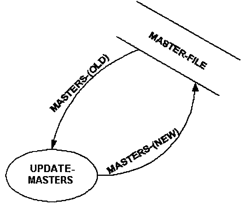
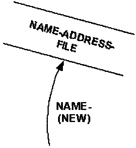
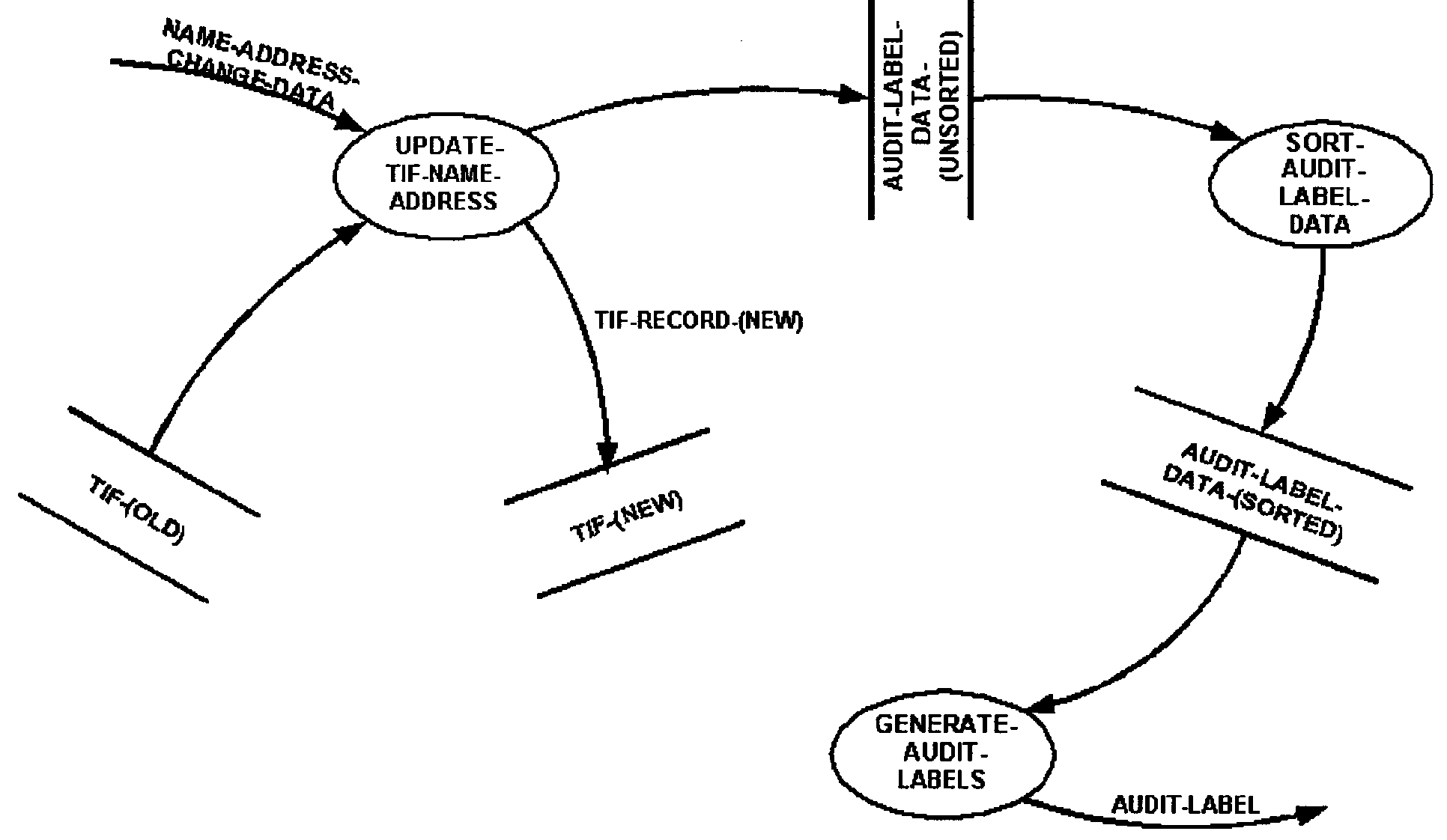
As an example Figure 2.5.11-2 illustrates a data store or file not shown in Diagram 0. This is because the file is internal to the processing in process 3 (as though it is concealed inside the bubble). The file and all its data streams are shown when process 3 is diagrammed.
-
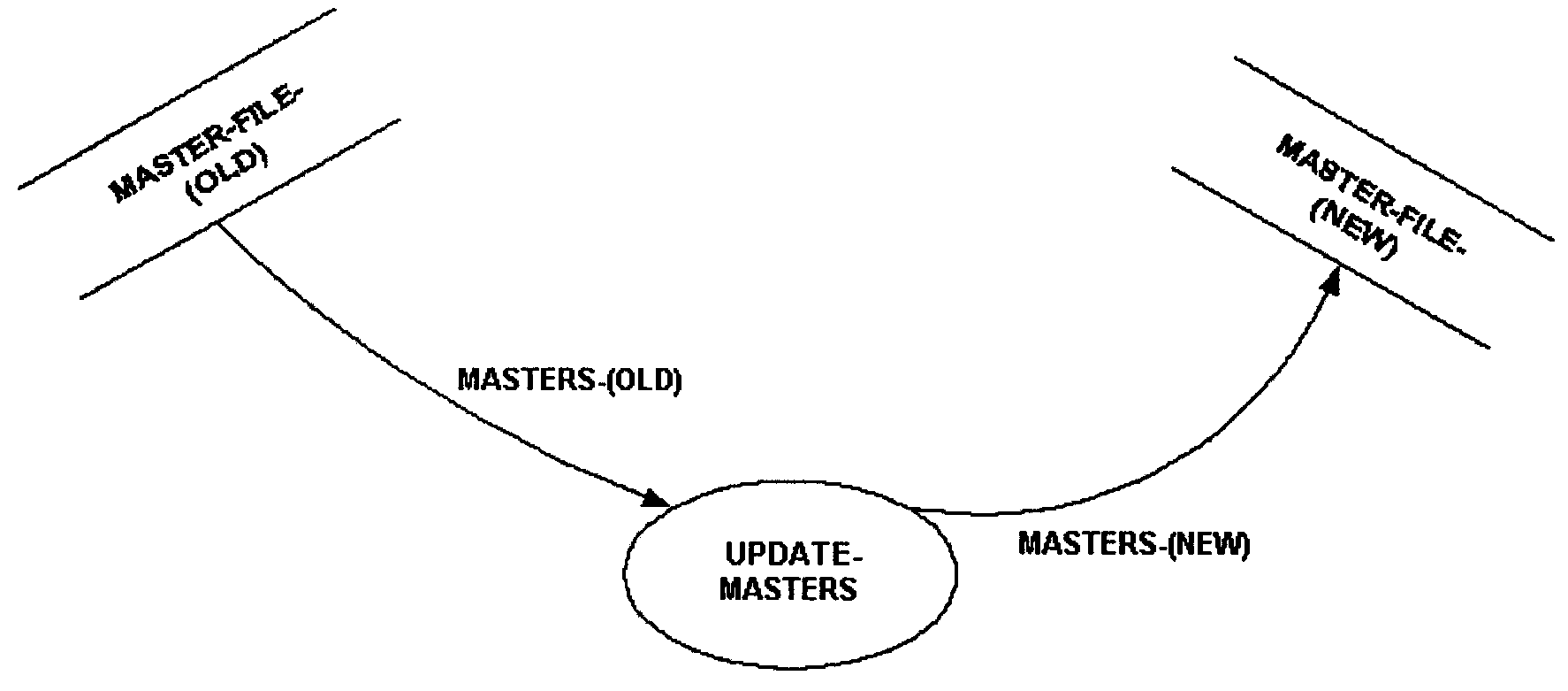
As an example Figure 2.5.11-3 for Diagram 0 illustrates a file being used by processes 2 and 3.
-
In applying structured analysis, develop and use the following types of data flow diagrams:
-
Current physical data flow diagram, see IRM 2.5.11.4.2.2.5.1
-
Current logical data flow diagram, see IRM 2.5.11.4.2.2.5.2
-
New logical data flow diagram, see IRM 2.5.11.4.2.2.5.3
-
New physical data flow diagram, see IRM 2.5.11.4.2.2.5.5
-
-
Use this type of data flow diagram to model the current physical environment. This type of data flow diagram models the physical characteristics of an existing system such as: department names, physical location, organizations, people's names, and mechanical or operational devices.
-
Use this type of data flow diagram when modeling a system for the first time. Since the user is more familiar with the physical terminology, get the user's approval of the accuracy of the model of the existing system before continuing analysis.
-
Make a current physical data flow diagram by removing physical considerations and constraints. For instance, replace department names with the actual processing functions within that department. The logical model must depict how the data is being transformed, not who or what is transforming it.
-
To accommodate required changes to a system, reexamine the rationale behind the why and the way processes are done. Modify the depiction, processes, and data stores to visualize the model’s new state to be considered and implemented.
-
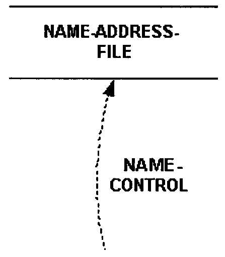
When designating files on logical data flow diagrams in which data from an old version of a file is being transformed into data for a new version of that same file, show the old and new versions of the file. Figure 2.5.11-13 illustrates a data transformation.
-
The data flow diagrams that result from this technique are the actual maintainable documentation required within the functional specification package.
-
In the final aspect of data flow diagram development, balance the implementation of the ideal system (as represented by the new logical data flow diagrams) against the realities of time and cost constraints. Consider feasibility and impact studies, cost/benefit analysis, and other variables until an appropriate compromise physical model is selected.
-
Make physical decisions, e.g., which data stores will be data bases as opposed to sequential files, and consider "packaging."
-
Do not allow the data flow diagrams to become too physical, because this will limit the choices available to the designer. Depict functional processes as opposed to organizational entities affecting the system, e.g., departments or divisions.
-
If a decision is made during creation of the physical data flow diagram to use a single random access file, designate it on the new physical data flow diagram (but not on the logical data flow diagram). Figure 2.5.11-14 illustrates random file access depicted on a data flow diagram.
-
If the file is to be sequentially processed, or there is uncertainty how it will be processed, depict the file on the new physical data flow diagram as Figure 2.5.11-15 illustrates.
-
Leveling is the partitioning of a large system into manageable units, resulting in system documentation that is easier to comprehend. Top-down analysis and reanalysis of processes and data (partitioning and re-partitioning) produce a high-level overview for management and lower, more detailed levels for the designer and users. A leveled data flow diagram set comprises:
-
The top-level diagram, called the context diagram, which defines the boundary of the system and consists of only one bubble that is labeled with an overall system descriptor. The system sources, sinks, inputs, and outputs are depicted; and the input and output data streams are shown to define the domain of the system.
-
Middle-level data flow diagrams are used when it is necessary to represent the system processes within the context diagram broken down into a more detailed level. They are the intermediate level between a context diagram and the functional primitives.
-
The lowest-level data flow diagram, called a functional primitive, represents a process that cannot be further decomposed. A functional primitive has no internal data streams and usually only a single input and single output.
-
-
Exhibit 2.5.11- 1 Illustrates the format for a leveled data flow diagram.
-
A diagram for which there is a lower–level diagram(s) is termed a "parent" diagram. For instance, in Exhibit 2.5.11-1, the context diagram is parent to Diagram 0 which is termed a "child" diagram. Diagram 0 also assumes the role of a parent to Diagram 2, which is the child of Diagram 0. Therefore, a diagram can be both a child of a higher level data flow diagram and a parent to a lower–level data flow diagram. However, the lowest level (Functional Primitive) data flow diagram can only be a child diagram because it cannot be further decomposed.
-
Each level of the data flow diagram is to reside on a separate page. The reader can follow the diagram leveling using the diagram and bubble numbering system as a guide.
-
There is no set number of levels. However, there is always at least a context diagram level and an associated lowest level. The number of middle level diagrams is dependent upon the complexity of the system being defined.
-
In the interest of readability, partition levels into about seven bubbles (plus or minus two bubbles).
-
Data flow diagrams have four main elements as the following:
-
External Entity (also known as actors, sources or sinks, and terminators): Produce and use data that flows between the entity and the system being diagrammed. The data flows are the inputs/outputs of the DFD and are normally placed at the boundaries of the diagram because they are external to the system.
-
Process: For explanation see IRM 2.5.11.4.2.6.2
-
Data Store: For explanation see IRM 2.5.11.4.2.7
-
Data Flow: For explanation see IRM 2.5.11.4.2
-
-
A data stream is one or more elements of data. A data stream is used to indicate a sharing of data. A data stream is graphically represented by an arrow that shows the direction for which data is being shared. Figure 2.5.11- 1 depicts a data stream.
-
Label all data streams with meaningful names and applicable naming standards. When a data stream has been logically transformed and this needs to be distinguished, do not create a new data name. Use a modifier to qualify the name and place it in parentheses after the data stream name. Figure 2.5.11-7 depicts data streams with modified names.
-
A router is used to subdivide a data stream or decompose data. A router is graphically represented by a right half circle. Figure 2.5.11- 3 depicts a router.
-
A collector is used to rebuild data streams or recompose data. A router is graphically represented by a left half circle. Figure 2.5.11- 4 depicts a collector.


-
A split data stream divides the routing of data. Unlike the case with the logical router and logical collector, no decomposing or recomposing of the data stream takes place. A split arrow is used to show the routing of a data stream to two or more destinations. A split data stream is graphically represented by a multi prong arrow. Figure 2.5.11- 5 depicts a split data stream as seen below.

-
A process represents a logical transformation of an incoming data stream(s) into an outgoing data stream(s). A process is a type of object that represents activity and constitutes a data flow diagram. A process name must consist of a transitive verb followed by a subject. Show a process by an ellipse or circle with a process name inside. Figure 2.5.11-12 shows these conventions as seen below.
-
For decomposition purposes, three types of processes are acknowledged:
-
Context process: A context process represents the scope of activity being analyzed and modeled. A context process represents the first level of decomposition for a related set of data flow diagrams. A context process is a process that comprises other processes and does not constitute another process. As a rule, a context process may not constitute another process.
-
Parent process: A parent process is a process that comprises other processes. As a rule, a parent process must constitute another process and comprise other processes .
-
Elementary process: An elementary process is a process that constitutes another process and does not comprise other processes. As a rule, an elementary process must not comprise other processes.
-

-
A Data Store (Database, File, and Table), represented by parallel lines, is a data stream, which is at rest (i.e., a temporary repository of data). Place the data store name between the parallel lines. Figure 2.5.11-13 illustrates a data store.

-
Use the arrows to represent reads, writes, or other accesses to a data store and may be used in any appropriate combination. Figure 2.5.11-14 illustrates the accessing of or reading from a data store.
-
Figure 2.5.11-15 illustrates the updating of or writing to a data store.
-
When diagramming a file key accessing a data store, the key is optional. Only show the key on a physical data flow diagram (i.e., after it is decided that the file media will be direct access). Figure 2.5.11-12 illustrates a file key accessing a data store.
-
An access key is an optional figure that is represented by a dashed line with a name; and is only used to represent a key accessing a random–access disk file. Figure 2.5.11-8 illustrates an access key to a data store.

-
Represent a Source/Sink (e.g., External Entity, External Input and Output) by a rectangle. A source or sink is a person or organization, external to the context of a system that is a net originator or receiver of system data. Place the source/sink name inside the rectangle. Figure 2.5.11-9 illustrates a source/sink.

-
Introduce a sort as a process bubble only when it is logically required. If the sort process is being shown as a bubble is sorting an input file, and putting out a sorted file, then show these files on the data flow diagram. Name the data stores only, not the data streams.
-
Figure 2.5.11-16 provides an example (of a sequential file update or an update where the decision as to whether it will be random or sequential has not been made) that illustrates a sort.
-
An off-page connector is represented by a circle and arrow. Avoid continuation pages because they make the data flow diagram less readable. When a data flow diagram must be continued onto another page and the diagram remains at the same level of decomposition, then, the off-page connector may be used. Write the sending and receiving page numbers within the respective circles. To avoid confusion, make the circles smaller than the process bubbles on your data flow diagram. Figure 2.5.11-17 illustrates the conventions used to depict off-page connectors.

-
Develop a definition for each data stream and data store on the data flow diagram, and is maintained in a system glossary. Ensure all the data definitions are defined as follows:
-
Data elements.
-
Data streams and groups of data elements contained within these data stores and all components referenced in the process specifications.
-
≡ ≡ ≡ ≡ ≡ ≡ ≡ ≡ ≡ ≡ ≡ ≡ ≡ ≡ ≡ ≡ ≡ ≡ ≡ ≡ ≡ ≡ ≡ ≡ ≡ ≡ ≡ ≡ ≡ ≡ ≡ ≡ ≡ ≡ ≡ ≡ ≡ ≡ ≡ ≡≡ ≡ ≡ ≡ ≡ ≡ ≡ ≡ ≡ ≡ ≡ ≡ ≡ ≡ ≡ ≡ ≡ ≡ ≡ ≡ ≡ ≡ ≡ ≡ ≡ ≡ ≡ ≡ ≡ ≡ ≡ ≡ ≡ ≡ ≡ ≡ ≡ ≡ ≡ ≡ ≡ ≡ ≡ ≡ ≡ ≡ ≡ ≡ ≡ ≡ ≡ ≡ ≡ ≡ ≡ ≡ ≡ ≡
-
Use IRS guidelines for the use of enterprise data dictionary, see reference in this subsection under d).
-
-
Define data in terms of its components and their relationship in the hierarchy. Define the following four types:
-
Data Element: This is the smallest piece of data that is not further decomposed.
-
Data Group: This is a data structure that consists of other data groups and/or data elements.
-
Data Stream (also called data flow): This is a pipeline along which information of known composition is passed, also termed as data in motion/data in transit.
-
Data Store: This is a temporary repository of data and is termed as data at rest. Data at rest also refers to data that is not actively moving from device to device, or network to network after the data arrives at its final destination.
-
-
External entities (sources and sinks) are not data, but must also be described in the system glossary or data dictionary.
-
The components of data definitions consist of two separate database definitions:
-
Data Attributes (DATA_ATTRIBUTES): This defines the appearance and behavior of the data type.
-
Data Criteria (DATA_CRITERIA): This is used to assign the object type to a file or directory, as seen in the example below:
Figure 2.5.11-20
Data Criteria
Criteria Description File name The file name must match a specified pattern. Use the NAME_PATTERN field for naming requirements. File location The path must match a specified pattern. Use the PATH_PATTERN field. File contents A portion of the file’s contents must match specified data. Use the CONTENT field. File mode The file must possess the specified permissions (read, write, execute, directory). Use the MODE field for required permissions. Symbolic links The typing is based on the file to which the object is linked. -
-
The following attributes describe and define the system components. They provide information critical to understanding the system under description:
-
Constraints
-
Contains
-
Description
-
Values/Meanings
-
-
Use the following cross-references to describe the relationships between system components, and provide information that enhances system understanding and maintainability:
-
Access Key To
-
Accessed By
-
Aliases/Modifiers
-
Input To
-
Output Of
-
Part Of
-
Provides
-
Receives
-
Updated By
-
Additional cross-references for common Process Specifications
-
-
A single data element may constitute a data stream; this is indicated on a data flow diagram when the element name is assigned to an arrow.
-
The following attributes define the data streams/elements:
-
Description: A narrative description of the element.
-
Values/Meanings: A list of valid values for an element and the meanings of those values.
-
-
Use the following cross-references to describe the relationships with other system components:
-
Access Key To: An alphabetical listing of data stores for which this data element is an access key.
-
Aliases/Modifiers: An alphabetical listing of other names for the same element (aliases), or qualifiers for the element name (modifiers).
-
Input To: If the element is a data stream, an alphabetical listing of processes that, as input accept the data stream.
-
Output Of: If the element is a data stream, an alphabetical listing of processes which are sources of the data stream.
-
Part Of: An alphabetical listing of data groups which contain this element.
-

-
Label all data streams with meaningful names and applicable naming standards. When a data stream has been logically transformed and this needs to be distinguished, do not create a new data name. Use a modifier to qualify the name and place it in parentheses after the data stream name. Figure 2.5.11-7 depicts data streams with modified names.
-
For more guidance on naming data, see IRM 2.152.3 Information Technology, Data Engineering, Naming Data Element(s)/Object(s).
-
A group may be a data stream, or it may be a component part of a larger group, data stream, or data store. The following attributes define the data streams/groups:
-
Description: A narrative description of the group.
-
Contains: A list of the elements and/or subordinate groups which constitute the data stream/group being defined; symbols are used to show the relationships between the contents.
-
-
Use the following cross-references to describe the relationships with other system components:
-
Access Key To: An alphabetical listing of data stores for which this data group is an access key.
-
Aliases/Modifiers: An alphabetical listing of other names for the same group (aliases), or qualifiers for the group name (modifiers).
-
Input To: If the group is a data stream, an alphabetical listing of processes that, as input, accept the data stream.
-
Output Of: If the group is a data stream, an alphabetical listing of processes which are sources of the data stream.
-
Part Of: An alphabetical listing of larger data groups which contain this group.
-
-
The following attributes define the data store:
-
Description: A narrative description of the data store.
-
Constraints: A narrative description of items, rules, regulations, etc. affecting the data store; e.g., required password security or response time criteria for database access.
-
Contains: A list of the elements and/or groups which constitute the data store; symbols are used to show the relationships between the contents.
-
-
Other data store definition related information:
-
Accessed By: This is an alphabetical listing of processes or external entities which use this data store as a source; the data store is shown as an input to these processes or external entities on the data flow diagram.
-
Updated By: This is an alphabetical listing of processes or external entities which change or reorder the contents of the data store.
-
Aliases/Modifiers: This is an alphabetical listing of other names for the same data store (aliases), or qualifiers for the data store name (modifiers).
-
Part Of: This is an alphabetical listing of larger data stores (such as a database) which contain this element.
-
-
External entities are defined by the following:
-
Description: This is a narrative description of the external entity.
-
Provides: This is an alphabetical listing of data stream(s), which the external entity provides as input to the system.
-
Receives: This is an alphabetical listing of data stream(s), which the external entity receives as output from the system.
-
-
When a system is using both a glossary and data dictionary, some data will be defined in both. This is most likely to occur in the case of data streams on the context diagram that enter and exit the system, and with data elements. If it happens that the data is defined in both and any attributes are the same, state in the system glossary, see Data Dictionary.
-
Define the contents of data in the "Contains" attribute. Data, except for data elements, is composed of and defined by lower–level data components. Show the relationships between these data components in the "Contains" attribute using a symbol convention.
-
Unless the use of an automated data dictionary precludes usage, then refer to Figure 2.5.11-22 for the symbols to be used to list the contents of data.
-
Exhibit 2.5.11- 2 provides the symbols used to define data.
-
An alias is a data name that is synonymous with a more commonly accepted data name of a data stream, data store, data group, or data element. An alias is created when the same data is labeled with more than one data name (i.e., the commonly accepted name and the alias name(s)). See IRM 2.120.12 Information Technology, Solution Engineering, Naming Data Element(s)/Object(s) for more data naming guidance.
-
Aliases generally occur for three reasons:
-
Different users have different names for the same form, etc.
-
An analyst inadvertently introduces an alias in the data flow diagram.
-
Two analysts working independently with the same data stream give it different names.
-
-
This subsection provides guidance on using the results from analysis as the basis for software design.
-
If a data flow diagram has not been evenly partitioned, the diagram will combine some detail and some higher levels of abstraction. In this case, perform a top-down partitioning of the data flow diagram by:
-
Replacing any problem bubble by its "child" network and then connecting the data flows.
-
Grouping into sets to minimize interfaces.
-
Allocating one top-level bubble per set.
-
Renumbering and renaming everything.
-
-
As the new physical data flow diagrams are being developed, both the analyst and the designer must consider certain physical details. Unless a data flow diagram is small and limited in function, it will need to be "packaged". Packaging is the process of subdividing the data flow diagram processes into related groups of processes; and each of these related groups of processes evolves into a separate structure chart that will be created during the software design. The following physical boundaries and constraints have a bearing on the packaging of a data flow diagram set:
-
Man/machine boundary-separates manual processes from those performed on computer equipment.
-
Hardware boundary-separates processes, which must be performed on different types of computer equipment.
-
Batch/on-line/real time boundary-various functions of a system may be on-line, real time, or batch mode depending on the speed requirements for data retrieval, display, availability, etc.
-
Cycle or timing boundary-some processes must be run daily, while others only need to be run once a week, month, or year.
-
Commercial software-some processes may be accomplished using vendor-supplied software.
-
Security/safety needs-security and safety requirements may cause the addition of otherwise unnecessary boundaries and intermediate data stores. This includes audit, back-up, recovery, and checkpoint/restart requirements.
-
Resources-some processes may not be able to be run at the same time because of limited resources, (e.g., the job is too large for computer capacity).
-
-
All systems, whether structured or not, require descriptions of the procedures that determine how inputs are to be transformed into outputs. As these procedures increase in complexity, English narrative descriptions become a more ambiguous and less acceptable means to specify these transformations.
-
Structured analysis introduces the process specification, a written description, and explanation of the processing which takes place within a data flow diagram process bubble.
-
Only use structured English, decision tables, or decision trees to write the procedures section of a process specification.
-
The three attributes associated with all process specifications are (in appropriate order):
-
Description: A narrative describing the purpose and objective of the process.
-
Constraints: A narrative description of the process constraints. This section usually is not needed, but may be used to specify nonprocedural requirements. An example is a timing requirement such as a report that must be generated only on the last day of the month. Pertinent characteristics of the process, e.g., input and output volumes, peaks and seasonality of the input and output data flows are other possible constraints.
-
Procedures: Use structured English, decision tables, or decision trees to describe in detail the criteria governing the transformation of input data streams into output data streams. Convey what has to be done, not how it is to be accomplished.
-
-
There are two types of process specifications:
-
Primitive Level Process Specifications, see IRM 2.5.11.5.2.1
-
Higher Level Process Specifications, see IRM 2.5.11.5.2.2
-
-
This type of process specification defines primitive level (lowest level; not further decomposed) data flow diagram process bubbles. This specification must contain: the description, procedure(s) attribute(s), and as applicable constraint(s) attribute(s).
-
Do not address physical requirements, e.g., telecommunications devices, in the written description. Describe physical information in the constraints section, but only when essential.
-
Ensure that the process specifications stress what needs to be accomplished, not how it is to be accomplished.
-
Develop a process specification for each bubble.
-
Entitle each process specification with the process name and number of its associated bubble on the data flow diagram.
-
Define the transformation of input data into output data for process specification.
-
Avoid redundancy between the process specification, and other tools in the functional specification package.
-
Use the data names as shown in the data flow diagrams, and the date definitions in the process specification.
-
Use Structured English decision table, or decision tree format to write the procedures attribute.
-
Structured English is English-like instructions with a limited selection of sentence structures that reflect processing actions. An algorithm can be written in English-like programming syntax without consideration to the actual programming language for future use. Structured English is used to verify the business logic, which can then be coded in any programming language. Common terms are used, such as IF-THEN-ELSE.
-
Structured English uses a limited vocabulary consisting of:
-
Strong action verbs
-
Direct and indirect objects that are defined in a glossary/data dictionary
-
As few adjectives and adverbs as possible
-
-
Do not write process specifications from a physical code-like perspective (i.e., in the worst case they contain detailed instructions as to control, working storage, physical media considerations, switch settings, etc.) as this will cause a significant decrease in "user friendliness".
-
Structured English that is simply pseudocode for program source code defeats the purpose of analysis, limits design options and flexibility, and creates a maintenance headache for analysts.
-
Structured English also uses a limited statement syntax consisting of simple imperative sentences, closed-end decisions, closed-end repetitions, or any combinations of the above.
-
Constructs have only one entry point and one exit point; they create a linear presentation (one construct is done completely before another construct is begun), thus avoiding the confusion inherent in narratives that skip around. Procedures written in Structured English must be numbered in a consistent manner for readability and referencing purposes. Numbering the constructs helps facilitate citing or referencing within the Procedures Section of a process specification.
-
All Process Specification functions must be described using only the three constructs discussed below.
-
Use this construct to present a sequence of steps to be taken in order. It consists of imperative sentences, each of which is ended with a period and is indented equally in the construct. Indentation signifies the relationships and dependencies of statements within the various constructs. Figure 2.5.11-23 provides an example of a sequence construct.

-
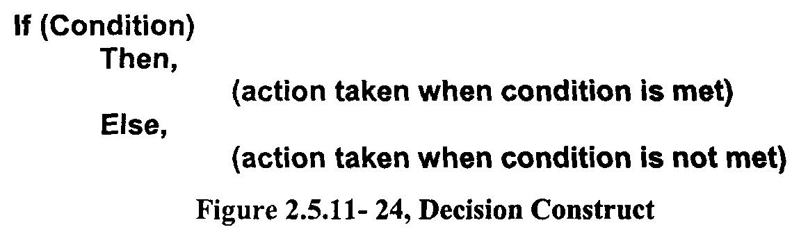
Use this type of construct to select an action from among mutually exclusive alternative actions based upon the outcome of a specific condition. There are two versions of this construct, the If-Then-Else format and the Select-Case format.
-
Use the "If-Then-Else" format when there are only two alternatives.
-
Write the "Else" or the "Then" statement of the decision showing no action when there is no action to be taken.
-
The "Else" statement may be omitted (unless it is being used as an end marker for readability).
-
-
Figure 2.5.11-24 illustrates the If-Then-Else format.
-
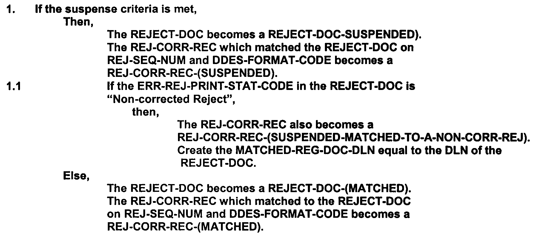
Figure 2.5.11-25 provides an example of an If-Then-Else Decision Construct.
-
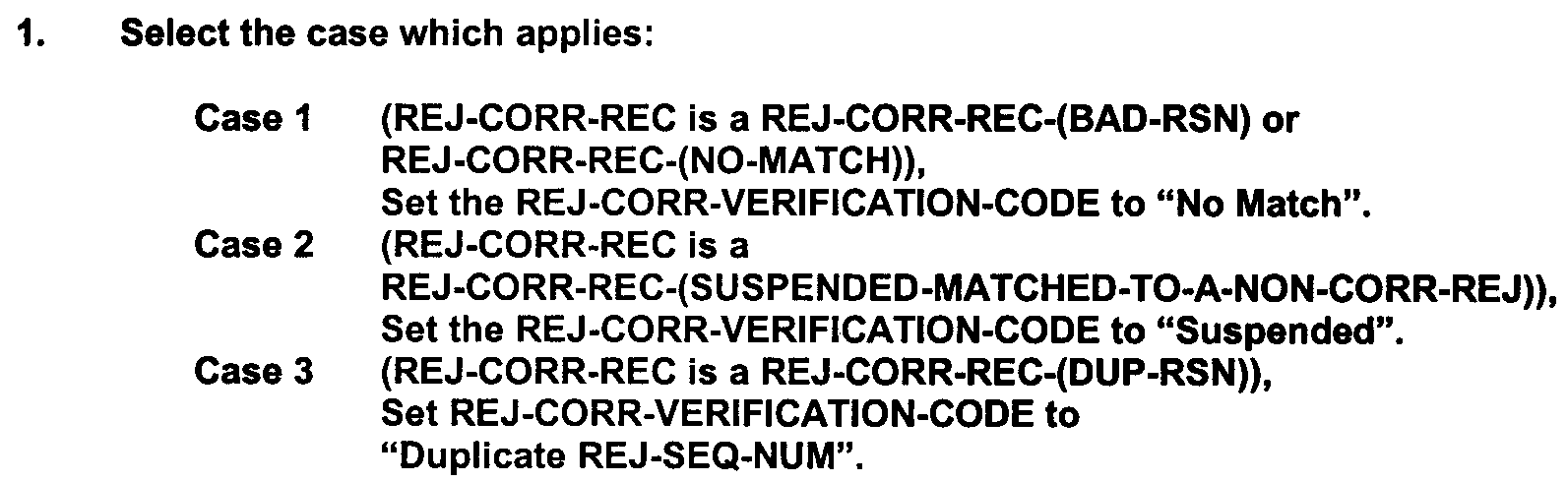
Use the "Select-Case" format when there are more than two alternatives, each mutually exclusive. Number each case, enclose in parentheses, and end with a comma. Once a case is selected and its action taken, ignore the subsequent case statements. Figure 2.5.11-26 provides an example of a Select-Case Decision Construct.
-
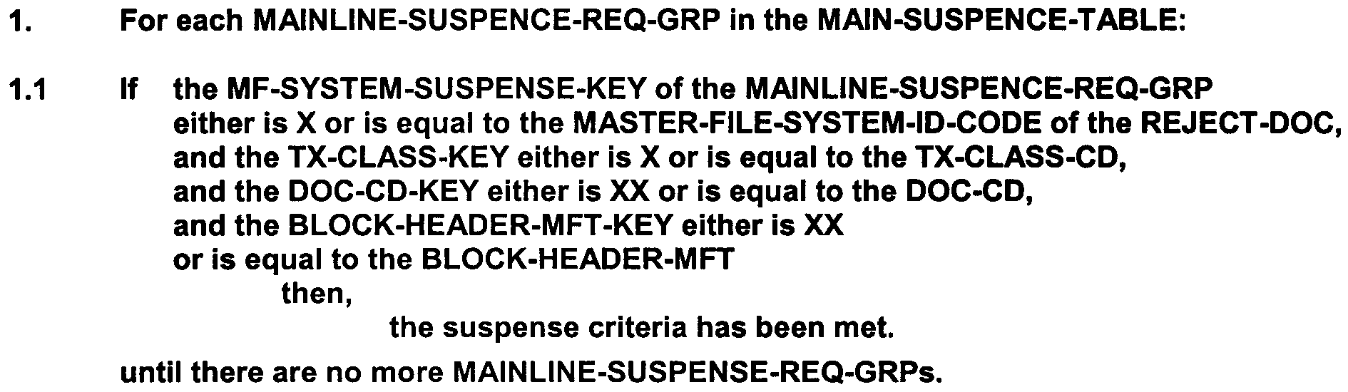
Use the "Repetition Construct" to show action performed until some condition occurs to cause the action(s) to cease. Figure 2.5.11-27 illustrates a Repetition Construct.
-
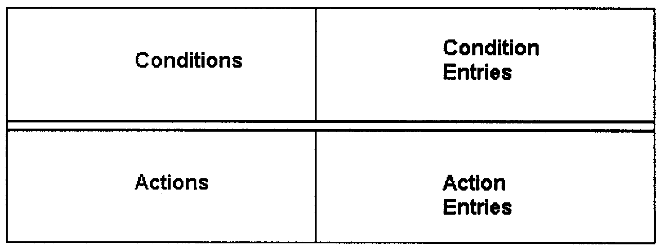
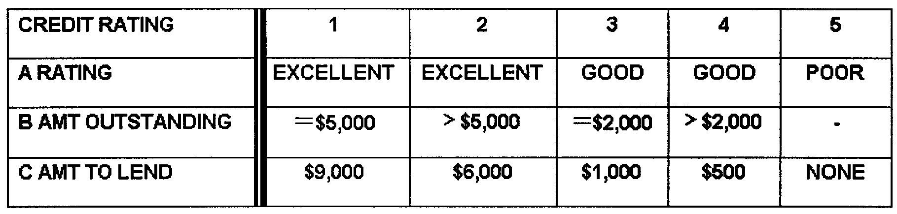
Decision tables are a concise, and efficient way of specifying processes which have numerous combinations of conditions in order to perform a specific action. Figure 2.5.11- 28 illustrates the format of a decision table. Exhibit 2.5.11- 3 illustrates a procedure, and a decision table that expresses the same procedure.
-
Figure 2.5.11- 29 provides an example of a decision table.
-
A decision table comprises four types of sections, the following explains these sections:
-
Conditions Section: Lists the conditions or statements that affect the process being specified and must be considered in performing the process being specified.
-
Condition Entries Section: Indicates whether the condition is met or not. This section is subdivided into vertical columns that are generally numbered and are known as rules. The blocks within the condition entries section, when filled in, contain the responses to the conditions listed in the conditions section.
-
Actions Section: Lists those actions that may be taken in to perform the process.
-
Action Entries Section: This section is also subdivided into the same vertical columns or rules as the condition entries section. The blocks contain either an "X" (meaning perform the action) or either a " " or a "=" (meaning the action does not apply).
-
-
Exhibit 2.5.11- 3 illustrates the use of a narration and a decision table to describe the same procedure. For the purposes of this exhibit, a procedure to determine who will approve the selection and acquisition of contractual services is being used.
-
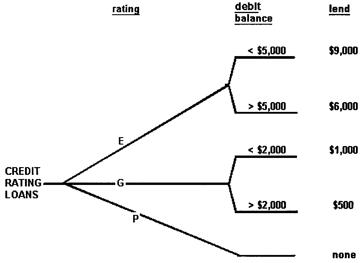
A decision tree is a graphic representation of a decision table; it communicates the same information in a different form. Figure 2.5.11- 29 provides an example of a decision table. Figure 2.5.11- 30 depicts a decision tree that expresses the decisions expressed in Figure 2.5.11- 29.
-
Some processes are shared by different systems or are used more than once within a single system. These common processes are designated by adding the suffix "(COMMON)", capitalized and placed in parentheses, to the end of the process name.
-
In addition to the three attributes which apply to all process specifications, there are three cross-references associated with common process specifications:
-
Maintained by the organizational identification (branch, section, etc.) of those who have maintenance responsibility
-
Last Revision month, day, and year of the latest revision
-
Used By organizations that use the Process Specifications
-
-
The first appearance of the common process specification in a data flow diagram set must list the "Description" attribute; may list the "Constraints" and "Procedures" attributes; and must list the "Maintained By" and "Last Revision" cross-references. Any subsequent occurrences of the common process specification need only list the "Description" attribute.
-
Each common process specification is the maintenance responsibility of one project team or organizational area, and only those responsible are authorized to make changes to a specification. Any organizational area may use the specification, but the group with the maintenance responsibility must notify the users of any changes and revisions.
-
Exhibit 2.5.11- 4 provides an example of the first and then subsequent occurrence of a common process specification.
-
CASE is a technique that uses powerful and programs/software to help system analysts or programmers develop and maintain information systems. Some CASE tools obtain specifications and generate the codes. CASE is used to ensure a high-quality defect-free software development and reduce the amount of repeatable work.
-
CASE ensures a check-pointed and disciplined approach, and assist designers, developers, testers, managers, and stakeholders to collaborate on the project milestones. The types of CASE tools are the following:
-
Upper CASE - Tools used in planning, analysis and design stages of SDLC.
-
Lower CASE - Tools used in implementation, testing and maintenance.
-
Integrated CASE - Combination of Upper CASE + Lower CASE tools.
-
Report Generator - A computer program whose purpose is to take data from a source such as a database, XML stream or a spreadsheet, and use it to create a document format.
-
Analysis Tools - Used to eliminate inconsistent, or incorrect specification through the creation of diagram and data flow.
-
Central Repository - A central place of storage where product specifications, requirement documents, related reports and diagrams e.g., in the IRS "DocIT" is a primary central repository.
-
Code Generator - A tool or resource that generates code from a programming language such as converting syntax to machine language that can be read by the computing system.
-
-
The categories of CASE Tools are:
-
Analysis - This tool helps with obtaining requirements check for any inconsistency, errors in the diagrams, data redundancies or erroneous omissions (software example Accept 360).
-
Change Control - This pertains to changes made to the software after the baseline is fixed, or when the software is first released, and provides Automatic Change Tracking, File Management, Code Management. Change Control relates to the following models:
• Kotter’s 8 Change Model - See John Kotter’s Eight Step Change Model https://portal.ct.gov/-/media/SDE/Turnaround/School-Improvement-Resources/Kotters_model.pdf.
• Kurt Lewin’s Change Model - Kurt Lewin used the analogy of how an ice block changes its shape to transform into a cone of ice to represent change.(Unfreeze - Change - Freeze), see https://www.managementstudyguide.com/kurt-lewins-change-management-model.htm.
• ADKAR Analysis - Represents: "A" = Awareness," D" = Desire, "K " = Knowledge, "A" = Ability, and "R" = Reinforcement, see https://www.prosci.com/adkar/adkar-model. -
Configuration Management - This pertains to automatic tracking of Version, Revision and Release management, Baseline Configuration management, and Change Control (software example Git and Fossil).
-
Design - Used to help the software designer to design the block structure of the software. Provides detailing of each module and interconnections among modules. (software examples: SmartBear-ReadyAPI and SoapUI).
-
Diagramming (Forward engineering) - Used for diagrammatic and graphical depictions of the data and system processes; (software example - MS Visio).
-
Documentation - Generates documents for technical and end users, e.g. Training, User, and Installation manuals (software example - MS Office).
-
Maintenance - Provides automatic logging and error reporting, error ticket generation, and root cause analysis (software example - Bugzilla for defect tracking, ).
-
Process Modelling - The process for creating software process models which is used to develop software, and help the managers to choose a process model or modify it as per the requirement of software product.
-
Programming (Reverse engineering) - These tools consist of programming environments like Integrated Development Environment (IDE), with in-built modules library and simulation tools, and provide all-inclusive help in building software product and include features for simulation and testing (software example - Eclipse).
-
Project Management - Use for project planning, cost and effort estimation, project scheduling and resource planning (software example - MS Project).
-
Prototyping - Simulated version of the intended software product and provides the initial mock-up of the product and simulates a few aspects of the actual product, (software examples: Serena Prototype Composer and Mockup Builder).
-
Quality Assurance - Software that monitors the engineering process and methods adopted to develop the software product to ensure conformance of quality according to organization standards (software examples: AppsWatch, Eclipse Junit, and SoapTest).
-
Web Development - Assist in designing web pages with all the elements: forms, text, script, and graphic (software examples: Adobe Edge Inspect, Foundation 3 and Brackets).
-
-
The advantages of using CASE models are:
-
When the emphasis is placed on software redesign and testing, the servicing cost of a product over the life cycle is reduced.
-
The overall quality of the product is improved as an organized approach is sought during the development process.
-
Opportunities to meet real-world requirements are more easily achievable with a computer-aided software engineering approach.
-
Provide a source of higher quality end products that efficiently fulfill the user requirements.
-
-
Joint Application Development (JAD) is a methodology that involves user-oriented fact-finding techniques for obtaining system specifications requirements pertaining to future development projects. A series of workshops must be organized with teams composed of end users, management, IT staff, and other relevant stakeholders.
-
The features of the Joint Application Development Model are:
-
Structured and focused.
-
Elimination of errors.
-
Forum for researching various talking points.
-
-
Three RAD categories are:
-
Phased development : Bread into a series of versions that are developed sequentially.
-
Prototyping :Building a scaled-down working version of the system.
-
Throw-away prototyping : Design prototype where risks are minimized.
-
-
Rapid Application Development is a type of Agile software development model that was created during the 1980s. Its invention was a direct result of the drawbacks of regressive traditional development models such as the Waterfall Software Development Model. One of the major flaws in the Waterfall model is once the software enters the testing phase it becomes exceedingly difficult to alter its core functions and features. Ultimately, resulting with software that might not fit your evolving requirements.
-
The RAD model is based on rapid prototyping and quick feedback from stakeholders over the length of the development and testing cycle with minimum planning. RAD enables low-code rapid application development through which business can roll-out new applications faster using IRS teams composed of end users, management, and IT staff to complete the projects.
-
The IRS Requirements Engineering Program Office created the term “Visualization” as an alias for prototyping. The concept of Visualization in software development is to allows project teams to quickly produce, document, and verify requirements for any project with a User Interface (UI). This method provides more clarity instead of exclusively using text.
-
REPO is currently using "Juntinmind Prototyper" as the enterprise standard tool to create prototypes. Visualization is a valid replacement for the following type of requirements:
-
Detailed user inputs
-
Informative text
-
Navigational flows
-
Information architecture
-
-
Use the Rapid Application Development methodology if the following criteria exist:
-
The lead Project manager and management’s must have buy-in.
-
Clear user requirements must be established.
-
The reliability of the future system has been validated.
-
Schedule visibility - Must have full knowledge of the project schedule
-
Time - There is a tight deadline to meet, and the team must deliver a product that works and is efficient according to customer requirements.
-
-
≡ ≡ ≡ ≡ ≡ ≡ ≡ ≡ ≡ ≡ ≡ ≡ ≡ ≡ ≡ ≡≡ ≡ ≡ ≡ ≡ ≡ ≡ ≡ ≡≡ ≡ ≡ ≡ ≡ ≡ ≡ ≡ ≡ ≡ ≡ ≡ ≡ ≡ ≡ ≡ ≡ ≡ ≡ ≡ ≡ ≡ ≡ ≡ ≡ ≡ ≡ ≡ ≡ ≡ ≡ ≡ ≡ ≡ ≡ ≡ ≡ ≡ ≡ ≡ ≡ ≡ ≡ ≡ ≡ ≡ ≡ ≡ ≡ ≡ ≡ ≡ ≡ ≡ ≡ ≡ ≡ ≡ ≡ ≡ ≡ ≡ ≡ ≡ ≡ ≡ ≡ ≡ ≡ ≡ ≡ ≡ ≡ ≡ ≡ ≡ ≡ ≡ ≡ ≡ ≡ ≡ ≡ ≡ ≡ ≡ ≡ ≡ ≡ ≡≡ ≡ ≡ ≡ ≡ ≡ ≡ ≡ ≡ ≡ ≡ ≡ ≡ ≡ ≡ ≡ ≡ ≡ ≡ ≡ ≡ ≡ ≡ ≡ ≡ ≡ ≡ ≡ ≡ ≡ ≡ ≡ ≡ ≡ ≡ ≡ ≡ ≡ ≡ ≡ ≡ ≡ ≡ ≡ ≡ ≡ ≡ ≡ ≡ ≡
-
The primary deliverable that results from structured analysis is a functional specification package. After a system is defined using the tools of structured analysis, the resulting documentation must be packaged to derive the functional specification package.
-
Naming standards must be applied. Names, numbers, and all other identifiers must be consistent among deliverables where applicable.
-
Standard identifying information must be provided on every page of the analysis documents. Include the following types of information when applicable:
-
System name
-
Functional Specification Package number
-
Responsible organization (e.g., branch/section)
-
Operational/Revision date
-
Project Name/Project Number
-
-
A functional specification package comprises one context diagram. The scope of the functional specification package must be consistent with the scope of the context diagram. The functional specification package comprises:
-
Data flow diagrams, which graphically depict business processes and the data interfaces among these processes
-
Data definitions, which define and document the interfaces on the data flow diagrams
-
Process specifications, which specify the data transformations among the business processes
-
-
The two allowable ways of ordering the data flow diagrams and process specifications within a functional specification package. The data flow diagrams must be sequenced in ascending numeric order, and the process specifications placed immediately behind their associated data flow diagram or grouped together behind the entire data flow diagram set.
-
To maintain constancy among functional specifications packages developed for a system, one of the following methods must be used for sequencing:
-
Sequence the Process Specification in the same sequential order they would appear in if they were interspersed with the data flow diagrams
-
Sequence the Process Specifications in ascending numeric order (e.g., 1.0, 2.0, 2.1, 2.1.1, 2.1.2, 2.2, 3.0, 3.1, 3.2, 3.3, 4.0).
-
-
Enter all data definitions into a system glossary, and/or data dictionary. If a manual system glossary is being used, packaged it into the functional specification package.
-
In order to fully document a system, add other sections to a functional specification package. Graphics for projects that use terminals for processing must be organized into a "Screen Display" section.
-
Organize graphic formats for printed inputs and outputs such as reports, e.g., error registers into a "Print Report Layouts" section.
-
Add a "Table of Contents" and/or "Cross-Referencing" material to aid the reader in understanding and following the Functional Specification Package (FSP). Develop an alphabetical index of names of external entities, processes, data groups, and data elements; or a listing of external inputs and outputs, and processes to organize a Functional Specification Package.
-
Agile means the ability to respond promptly to change. This software development approach focuses on flexibility in the application delivery process where the iterative approach delivers time boxed tasks that are divided into specific features for customer requirement releases. Agile teams evaluate requirements and results continuously, which leads to the efficient implementation of change.
-
Developers using the agile approach must develop software which is both high-quality and high-value. The simplest way to develop high-value software is to implement the highest priority requirements first because this enables them to maximize stakeholder (Return On Investment) ROI. Since requirements change frequently you need a streamlined, flexible approach to requirements and change management. The Agile methodologies currently used by the IRS are the following:
-
Scrum: Scrum is a efficient way of delivering a project using a small team. It’s flexible, transparent, and light on overhead. It requires lots of communication between those small team members to operate at a high level. Scrum is an iterative and incremental framework that helps teams deliver high-quality products in a timely manner. Each iteration (Sprint) is time-boxed for (2- 4 weeks) and allow the team to break down complex projects into short achievable tasks. Scrum consist of the following roles:
• Product Owner (PO): This role is responsible for bridging the gap between the customer, business stakeholders, and developers. The product owner is an expert on the product and the customer's needs and priorities. The product owner works with the developers daily to help clarify requirements.
• Scrum Master: This role facilitates a team environment that contributes to Scrum success. Assist the PO to define task value, and communicates that value to the Scrum team so that they can deliver it on schedule.
• Scrum Team: A hierarchy does not exist in a Scrum team. The Scrum Team is a cross-functional and self-organizing group of developers who are mutually responsible for product delivery. A team is required to communicate and collaborate well together. -
Scaled Agile Framework (SAFe): This is a agile scaling framework that implements Scrum at an enterprise level, and involves enterprise-level decision-making created for multiple development teams working on complex, large-scale projects. SAFe’s operates at four levels as the following:
• Team Level: Almost identical to Scrum. An organization may have a number of teams working in an agile fashion toward a particular goal or solution.
• Program Level: SAFe at the program level uses the concept of the Agile Release Train (ART) to deliver the value expected from a specific project. Scrum teams members (typically comprises 50 to 125), deliver value by using an incremental and iterative approach where time is divided into equal length sprints of two weeks.
• Large Solution Level: Involves two or more ARTs coordinated as a solution train.
• Portfolio Level: The portfolio level is the highest level where executives and leaders determine the organization’s visions, business goals, and strategies. SAFe aids organizations to handle challenges like funding, product road mapping, and management of changes. -
Kanban: Best used for daily task management and execution. This method operates on the pull system (i.e., your work starts when there is demand for the a specific deliverable). Continuous improvement is important when managing workflows while limiting how many tasks you process at a time.
-
-
Developers using the agile approach must develop software which is both high-quality and high-value. The simplest way to develop high-value software is to implement the highest priority requirements first because this enables them to maximize stakeholder Return On Investment ROI. Since requirements change frequently you need a streamlined, flexible approach to requirements and change management. Best practices for the IRS are the following:
-
Scrum Best Practices: For a good Scrum development process ensure the following events are established:
• Run Daily Scrum (Stand-up) Meetings: These meeting are normally for 15 minutes at the same time every day to synchronize team members. The purpose of this meeting is to discuss what each team member has done since the last meeting, identify any impediments preventing them from completing their work, and plan for the next 24 hours.
• Burn Down Chart: Create a burn down chart as a graphical representation of work left to do for the team versus time.
• Capacity Chart: Create a Capacity chart or spreadsheet for the team’s "Total number of available hours " in the sprint. This is called the development team's Capacity. Available hours is calculated based on the number of development team members, their daily work schedules, the percentage each team member is allocated to the team, and planned days off or holidays.
• Product Backlog and Refinements: Ensure your product backlog list all the features and requirements that must be implemented in the products. The Product Owner normally manages the Product Backlog for users, stakeholders, managers and other customers to focus on what needs to be built next. When refining items from your backlog, you must ensure all stakeholders understand why the item was selected. During later interactions, the Scrum team need to continue to refine until all features are done unless determined the task not required.
• Conduct Scrum Ceremonies: The following ceremonies must be conducted by the Scrum Master:
□ Sprint Planning: This meeting is where the team comes together to plan out the work for the upcoming sprint and everyone has a shared understanding.
□ Daily Stand-up:
□ Sprint Review: The developers or project team must explain or demonstrate the work they accomplished during the sprint. If the sprint lasted two weeks, this meeting can be about 60 minutes. If your team completed a one-month sprint, this meeting can last up to four hours. The key purpose of this meeting is to highlight the value the project delivers to the IRS and demonstrate the functionality of the deliverables.
□ Sprint Retrospective: After a sprint, the team must collaborate to determine what worked well, and how they can improve. This is a very important aspect for continuous improvement, development; and ensures that the team is learning and progressing to achieve their goals. This meeting can last 90 minutes.
-
SAFe Best Practices: When applying Agile at Scale you must know the answers for the following questions:
:
• What is the size of the development team, small ( 7 - 10 ) or large (100+)? A small team is used for Scrum methods? The larger teams with sub-teams and cross-functional roles are used for SAFe.
• System Complexity:
□ What are the system features?
□ What is the new technology that will be integrated?
□ What is the number of external systems that must communicate with the new system?
□ What are the independent systems being integrated and the number of users to accommodate?
□ What are the security requirements?
• Duration:
□ How long will the system be in development, operations and sustainment?
• Consider holding a Scrum of Scrums team coordination meeting. This meeting consist of members from each project team and sub-team that typically addresses the functionality, concerns and impediments of their initiatives.
□ Positive outcome: This inter-team coordination helps ensure the correct information, issues, statistics, and risks are communicated among teams. -
Kanban board: This board makes it easy for the team to see the current status of all current work items and who is responsible for each task. The concentration is around visualizing tasks and continuous flow. This board has at least three columns (Backlog, Work-In-Process, and Completed work).assist with project efficiency by cutting out wasted time and resources. To ensure the team is working on the most valuable tasks Kanban has 4 principles:
• Visualize the Work: Add a column for your current work, existing processes and practices (can be taken from the Sprint/Iteration Backlog).
• Limit the Work-In-Progress (WIP): Add a column that displays each team member’s designated the work item(s) that they will speak about in the Daily Stand-up meeting.
• Continuous Improvement: Follow the concept of continuous improvement by delivering changes in small increments. Teams must consistently find ways to improve processes and product quality.
• Done: Display a column of work items that are completed.
-
-
For information on Agile Principles see https://scaledagileframework.com/lean-agile-mindset/
-
For more information see the Agile Central Hub https://irsgov.sharepoint.com/sites/AgileCentral/.
-
The CIM Schema provides the actual model descriptions. Management schemas are the building-blocks for management platforms and management applications, such as device configuration, performance management, and change management. CIM structures the managed environment as a collection of interrelated systems, each composed of discrete elements.
-
Supplying a set of classes with properties and associations that provide a well-understood conceptual framework, CIM organizes information about the managed environment. The CIM Schema is structured into these distinct layers: core model, common model, and extension schemas.
-
The CIM schema is continuously changed to keep pace with technology. Users are to use the latest version of the schema, which is available at: https://www.dmtf.org/standards/cim/.
-
An example of the type of information that can be described by CIM is as follows:
-
Static information, (e.g., the capacity of a hard drive on a desktop computer, or applications and related subsystems installed on a server)
-
Dynamic information, such as the current bandwidth being used on a port, switch or router
-
-
CIM is based on an object-oriented programming model, in which inheritance causes subclasses to acquire characteristics from their parent classes.
-
For a visual example of a CIM model see Figure 2.5.11-31.
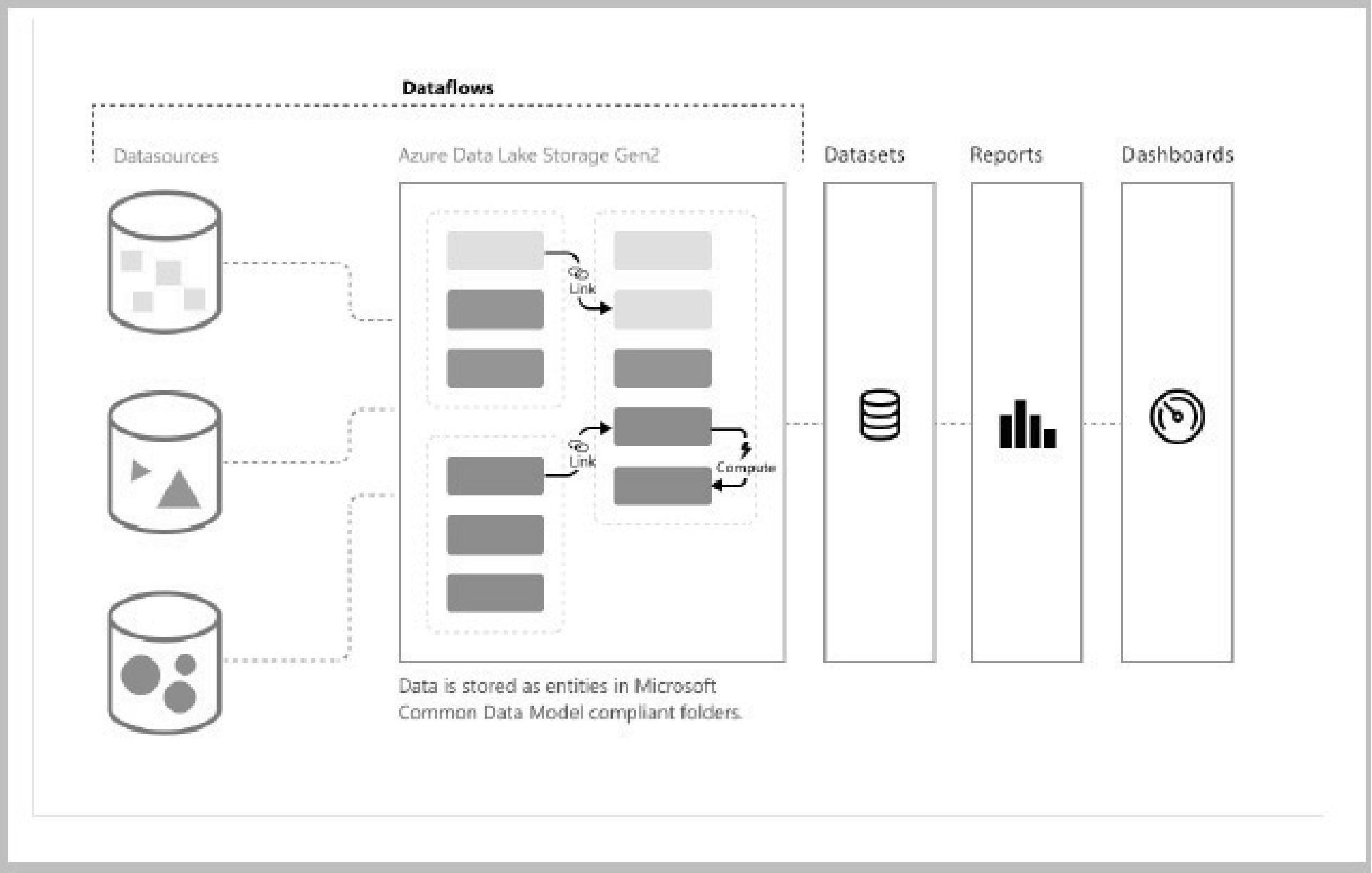
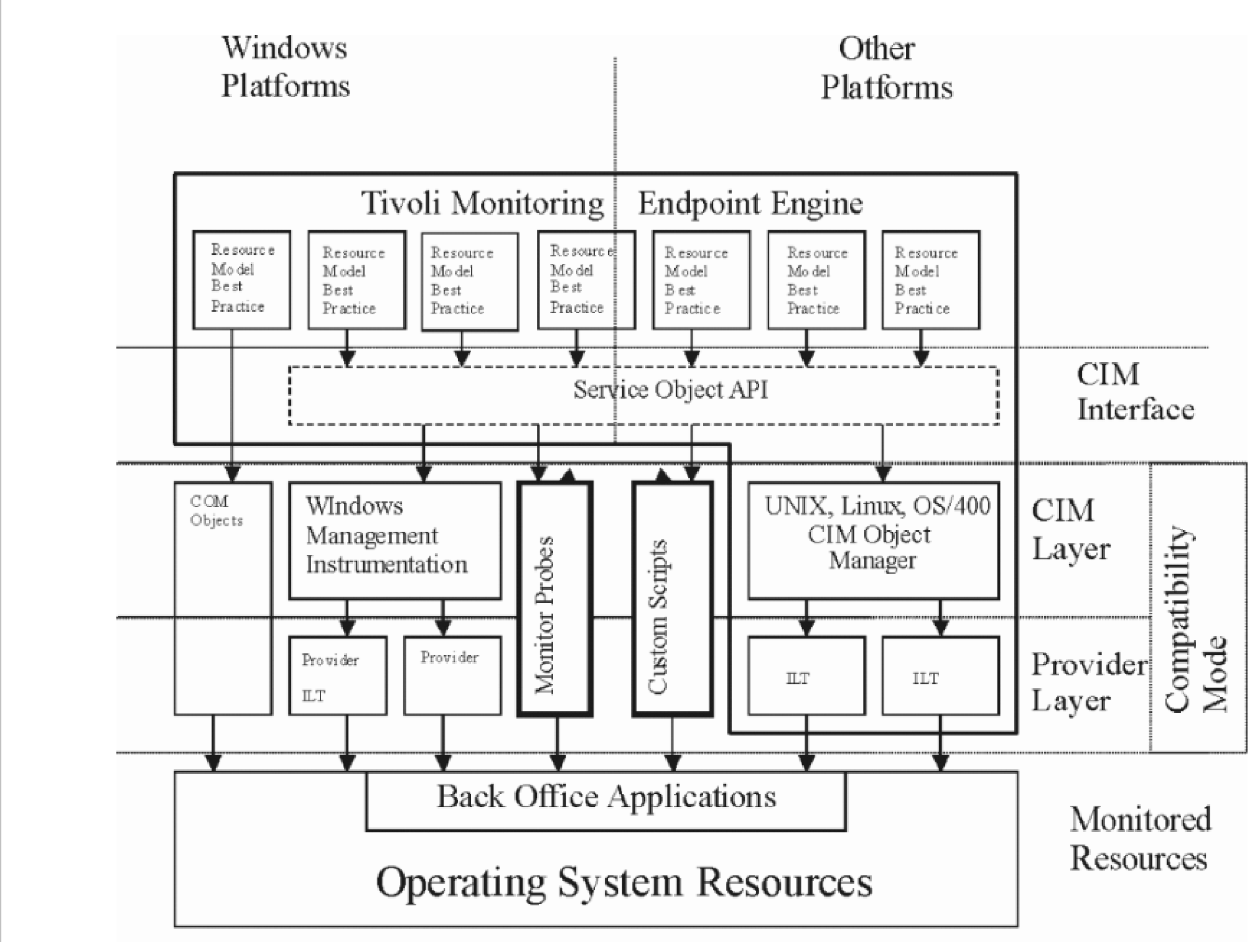
-
CIM allows three type of schemas as the following:
-
Core schemas: Defines the general areas of network and system management
-
Common schemas: Defines specific areas of management
-
Extension schemas : Defines the management of vendor-specific technologies
-
-
As DMTF defines the standard schema, major manufacturers like IBM, HP, Dell, and others provide "Extension" schemas that include their products.
-
≡ ≡ ≡ ≡ ≡ ≡ ≡ ≡ ≡ ≡ ≡ ≡ ≡ ≡ ≡ ≡ ≡ ≡ ≡ ≡ ≡ ≡ ≡ ≡ ≡ ≡ ≡ ≡ ≡ ≡ ≡ ≡ ≡ ≡ ≡ ≡ ≡ ≡ ≡ ≡ ≡ ≡ ≡ ≡ ≡ ≡ ≡ ≡ ≡ ≡ ≡ ≡ ≡ ≡ ≡ ≡ ≡ ≡ ≡ ≡ ≡ ≡ ≡ ≡ ≡ ≡ ≡ ≡ ≡ ≡ ≡ ≡ ≡ ≡ ≡ ≡ ≡ ≡ ≡ ≡ ≡ ≡ ≡ ≡ ≡ ≡ ≡ ≡ ≡ ≡ ≡ ≡ ≡ ≡ ≡ ≡ ≡ ≡ ≡ ≡ ≡ ≡ ≡ ≡ ≡ ≡ ≡ ≡ ≡ ≡ ≡ ≡ ≡ ≡ ≡ ≡ ≡ ≡ ≡ ≡ ≡ ≡ ≡ ≡ ≡ ≡ ≡ ≡ ≡ ≡ ≡ ≡ ≡ ≡ ≡ ≡ ≡ ≡"≡ ≡ ≡ ≡ ≡" ≡ ≡ ≡ ≡ ≡ ≡ ≡ ≡ ≡ ≡ ≡ ≡ ≡ ≡ ≡ ≡ ≡ ≡ ≡ ≡ ≡ ≡ ≡ ≡ ≡ ≡ ≡ ≡ ≡ ≡ ≡ ≡ ≡ ≡ ≡ ≡ ≡ ≡ ≡ ≡ ≡
-
≡ ≡ ≡ ≡ ≡ ≡ ≡ ≡ ≡ ≡ ≡ ≡ ≡ ≡ ≡ ≡ ≡ ≡ ≡ ≡ ≡ ≡ ≡ ≡ ≡ ≡ ≡ ≡ ≡ ≡ ≡ ≡ ≡ ≡ ≡ ≡ ≡ ≡ ≡ ≡ ≡"≡ ≡ ≡ ≡ ≡ ≡ ≡ ≡ ≡ ≡ ≡ ≡ ≡ ≡ ≡" ≡ ≡ ≡ ≡ ≡ ≡ ≡ ≡ ≡ ≡ ≡ ≡ ≡ ≡ ≡ ≡ ≡ ≡ ≡ ≡ ≡ ≡ ≡ ≡ ≡ ≡ ≡
-
≡ ≡ ≡ ≡ ≡ ≡ ≡ ≡ ≡ ≡ ≡ ≡ ≡ ≡ ≡ ≡ ≡ ≡≡ ≡ ≡ ≡ ≡ ≡ ≡ ≡ ≡ ≡ ≡ ≡ ≡ ≡ ≡ ≡ ≡ ≡ ≡ ≡ ≡ ≡ ≡ ≡ ≡ ≡ ≡ ≡ ≡ ≡ ≡ ≡ ≡ ≡ ≡ ≡ ≡ ≡ ≡ ≡ ≡ ≡ ≡ ≡ ≡ ≡ ≡ ≡ ≡ ≡ ≡ ≡ ≡ ≡ ≡ ≡ ≡ ≡ ≡ ≡ ≡ ≡ ≡ ≡ ≡ ≡ ≡ ≡ ≡ ≡ ≡ ≡ ≡ ≡ ≡ ≡ ≡ ≡ ≡ ≡ ≡ ≡ ≡ ≡ ≡ ≡ ≡ ≡ ≡ ≡ ≡ ≡ ≡ ≡ ≡ ≡ ≡ ≡ ≡ ≡ ≡ ≡ ≡ ≡ ≡ ≡ ≡ ≡ ≡ ≡ ≡ ≡ ≡ ≡ ≡ ≡ ≡ ≡≡ ≡ ≡ ≡ ≡ ≡ ≡ ≡ ≡ ≡ ≡ ≡≡ ≡ ≡
-
Figure 2.5.11-33
≡ ≡ ≡ ≡ ≡ ≡ ≡ ≡ ≡ ≡ ≡ ≡ ≡ ≡ ≡ ≡ ≡ ≡ ≡ ≡ ≡ ≡ ≡ ≡ ≡
≡ ≡ ≡ ≡ ≡ ≡ ≡ ≡ ≡ ≡ ≡ ≡ ≡ ≡ ≡ ≡ ≡ ≡ ≡ ≡ ≡ ≡ ≡ ≡ ≡ ≡ ≡ ≡ ≡ ≡ ≡ ≡ ≡ ≡ ≡ ≡ ≡ ≡ ≡ ≡ ≡ ≡ ≡ ≡ ≡ ≡ ≡ ≡ ≡ ≡ ≡ ≡ ≡ ≡ ≡ ≡ ≡ ≡ ≡ ≡ ≡ ≡ ≡ ≡ ≡ ≡ ≡ ≡ ≡ ≡ ≡ ≡ ≡ ≡ ≡ ≡ ≡ ≡ ≡ ≡ ≡ ≡ ≡ ≡ ≡ ≡ ≡ ≡ ≡ ≡ ≡ ≡ ≡ ≡ ≡ ≡ ≡ ≡ ≡ ≡ ≡ ≡ ≡ ≡ ≡ ≡ ≡ ≡ ≡ ≡ ≡ ≡ ≡ ≡ ≡ ≡ ≡ ≡ ≡ ≡ ≡ ≡ ≡ ≡ ≡ ≡ ≡ ≡ ≡ ≡ ≡ ≡ ≡ ≡ ≡ ≡ ≡ ≡ ≡ ≡ ≡ ≡ ≡ ≡ ≡ ≡ ≡ ≡ ≡ ≡ ≡ ≡ ≡ ≡ ≡ ≡ ≡ ≡ ≡ ≡ ≡ ≡ ≡ ≡ ≡ ≡ ≡ ≡ ≡ ≡ ≡ ≡ ≡ ≡ ≡ ≡ ≡ ≡ ≡ ≡ ≡ ≡ ≡ ≡ ≡ ≡ ≡ ≡ ≡ ≡ ≡ ≡ ≡ ≡ ≡ ≡ ≡ ≡ ≡ ≡ ≡ ≡ ≡ ≡ ≡ ≡ ≡ ≡ ≡ ≡ ≡ ≡ ≡ ≡ ≡ ≡ ≡ ≡ ≡ ≡ ≡ ≡ ≡ ≡ ≡ ≡ ≡ ≡ ≡ ≡ ≡ ≡ ≡ ≡ ≡ ≡ ≡ ≡ ≡ ≡ ≡ ≡ ≡ ≡ ≡ ≡ ≡ ≡ ≡ ≡ ≡ ≡ ≡ ≡ ≡ ≡ ≡ ≡ ≡ ≡ ≡ ≡ ≡ ≡ ≡ ≡ ≡ ≡ ≡ ≡ ≡ ≡ ≡ ≡ ≡ ≡ ≡ ≡ ≡ ≡ ≡ ≡ ≡ ≡ ≡ ≡ ≡ ≡ ≡ ≡ ≡ ≡ ≡ ≡ ≡ ≡ ≡ ≡ ≡ ≡ ≡ ≡ ≡ ≡ ≡ ≡ ≡ ≡ ≡ ≡ ≡ ≡ ≡ ≡ ≡ ≡ ≡ ≡ ≡ ≡ ≡ ≡ ≡ ≡ ≡ ≡ ≡ ≡ ≡ ≡ ≡ ≡ ≡ ≡ ≡ ≡ ≡ ≡ ≡ ≡ ≡ ≡ ≡ ≡ ≡ ≡ ≡ ≡ ≡ ≡ ≡ ≡ ≡ ≡ ≡ ≡ ≡ ≡ ≡ ≡ ≡ ≡ ≡ ≡ ≡ ≡ ≡ ≡"≡ ≡ ≡ ≡ ≡ ≡ ≡" ≡ ≡ ≡ ≡ ≡ ≡ ≡ ≡ ≡ ≡ ≡ ≡ ≡ ≡ ≡ ≡ ≡ ≡ ≡ ≡ ≡ ≡ ≡ ≡ ≡ ≡ ≡ ≡ ≡ ≡ ≡ ≡ ≡ ≡ ≡ ≡ ≡ ≡ ≡ ≡ ≡ ≡ ≡ ≡ ≡ ≡ ≡ ≡ ≡ ≡ ≡ ≡ ≡ ≡ ≡ ≡ ≡ ≡ ≡ ≡ ≡ ≡ ≡ ≡ ≡ ≡ ≡ ≡ ≡ ≡ ≡ ≡ ≡ ≡ ≡ ≡ ≡ ≡ ≡ ≡ ≡ ≡ ≡ ≡ ≡ ≡ ≡ ≡ ≡ ≡ ≡ ≡ ≡ ≡ ≡ ≡ ≡ ≡ ≡ ≡ ≡ ≡ ≡ ≡ ≡ ≡ ≡ ≡ ≡ ≡ ≡ ≡ ≡ ≡ ≡ ≡ ≡ ≡ ≡ ≡ ≡ ≡ ≡ ≡ ≡ ≡ ≡ ≡ ≡ ≡ ≡ ≡ ≡ ≡ ≡ ≡ ≡ ≡ ≡ ≡ ≡ ≡ ≡ ≡ ≡ ≡ ≡ ≡ ≡ ≡ ≡ ≡ ≡ ≡ ≡ ≡ ≡ ≡ ≡ ≡ ≡ ≡ ≡ ≡ ≡ ≡ ≡ ≡ ≡ ≡ ≡ ≡ ≡ ≡ ≡ ≡ ≡ ≡ ≡ ≡ ≡ ≡ ≡ ≡ ≡ ≡ ≡ ≡ ≡ ≡ ≡ ≡ ≡ ≡ ≡ ≡ ≡ ≡ ≡ ≡ ≡ ≡ ≡ ≡ ≡ ≡ ≡ ≡ ≡ ≡ ≡ ≡ ≡ ≡ ≡ ≡ ≡ ≡ ≡ ≡ ≡ ≡ ≡ ≡ ≡ ≡ ≡ ≡ ≡ ≡ ≡ ≡ ≡ ≡ ≡ ≡ ≡ ≡ ≡ ≡ ≡ ≡ ≡≡ ≡ ≡ ≡ ≡ ≡ ≡ ≡ ≡≡ ≡ ≡ ≡ ≡ ≡ ≡ ≡ ≡ ≡ ≡ ≡ ≡ ≡ ≡ ≡ ≡ ≡ ≡ ≡ ≡ ≡ ≡ ≡ ≡ ≡ ≡ ≡ ≡ ≡ ≡ ≡ ≡ ≡ ≡ ≡ ≡ ≡ ≡ ≡ ≡ ≡ ≡ ≡ ≡ ≡ ≡ ≡ ≡ ≡ ≡ ≡ ≡ ≡ ≡ ≡ ≡ ≡ ≡ ≡ ≡ ≡ ≡ ≡ ≡ ≡ ≡ ≡ ≡ ≡ ≡ ≡ ≡ ≡ ≡ ≡ ≡ ≡ ≡ ≡ ≡ ≡ ≡ ≡ ≡ ≡ ≡ ≡ ≡ ≡ ≡ ≡ ≡ ≡ ≡ ≡ ≡ ≡ ≡ ≡ ≡ ≡ ≡ ≡ ≡ ≡ ≡ ≡ ≡ ≡ ≡ ≡ ≡ ≡ ≡ ≡ ≡ ≡ ≡ ≡ ≡ ≡ ≡ ≡ ≡ ≡ ≡ ≡ ≡ ≡ ≡ ≡ ≡ ≡ ≡ ≡ ≡ ≡ ≡ ≡ ≡ ≡ ≡ ≡ ≡ ≡ ≡ ≡ ≡ ≡ ≡ ≡ ≡ ≡ ≡ ≡ ≡ ≡ ≡ ≡ ≡ ≡ ≡ ≡ ≡ ≡ ≡ ≡ ≡ ≡ ≡ ≡ ≡ ≡ ≡ ≡ ≡ ≡ ≡ ≡ ≡ ≡ ≡ ≡ ≡ ≡ ≡ ≡ ≡ ≡ ≡ ≡ ≡ ≡ ≡ ≡ ≡ ≡ ≡ ≡ ≡ ≡ ≡ ≡ ≡ ≡ ≡ ≡ ≡ ≡ ≡ ≡ ≡ ≡ ≡ ≡ ≡ ≡ ≡ ≡ ≡ ≡ ≡ ≡ ≡ ≡ ≡ ≡ ≡ ≡ ≡ ≡ ≡ ≡ ≡ ≡ ≡ ≡ ≡ ≡ ≡ ≡ ≡ ≡ ≡ ≡ ≡ ≡ ≡ ≡ ≡ ≡ ≡ ≡ ≡ ≡ ≡ ≡ ≡ ≡
-
-
≡ ≡ ≡ ≡ ≡ ≡ ≡ ≡ ≡ ≡ ≡ ≡ ≡ ≡ ≡ ≡ ≡ ≡ ≡ ≡ ≡ ≡ ≡ ≡ ≡ ≡ ≡ ≡ ≡ ≡ ≡ ≡ ≡ ≡ ≡ ≡ ≡ ≡ ≡ ≡ ≡ ≡ ≡ ≡ ≡ ≡ ≡ ≡ ≡ ≡ ≡ ≡ ≡ ≡ ≡ ≡ ≡ ≡ ≡ ≡ ≡ ≡ ≡ ≡ ≡ ≡ ≡ ≡ ≡ ≡ ≡ ≡ ≡ ≡ ≡ ≡ ≡ ≡ ≡ ≡ ≡ ≡ ≡ ≡ ≡ ≡ ≡ ≡ ≡ ≡ ≡ ≡ ≡ ≡ ≡ ≡ ≡ ≡ ≡ ≡ ≡ ≡ ≡ ≡ ≡ ≡ ≡ ≡ ≡ ≡ ≡ ≡ ≡ ≡ ≡ ≡ ≡ ≡ ≡ ≡ ≡ ≡ ≡ ≡ ≡ ≡ ≡ ≡ ≡ ≡ ≡ ≡ ≡ ≡ ≡
-
≡ ≡ ≡ ≡ ≡ ≡≡ ≡ ≡ ≡ ≡ ≡ ≡ ≡ ≡ ≡ ≡ ≡ ≡ ≡ ≡ ≡ ≡ ≡ ≡ ≡ ≡ ≡ ≡ ≡ ≡ ≡ ≡ ≡ ≡ ≡ ≡ ≡ ≡ ≡ ≡ ≡ ≡ ≡ ≡ ≡ ≡ ≡ ≡ ≡ ≡ ≡ ≡ ≡ ≡ ≡ ≡ ≡ ≡ ≡
-
≡ ≡ ≡ ≡ ≡ ≡ ≡ ≡ ≡≡ ≡ ≡ ≡ ≡ ≡ ≡ ≡ ≡ ≡ ≡ ≡ ≡ ≡ ≡ ≡ ≡ ≡ ≡ ≡ ≡ ≡ ≡ ≡ ≡ ≡ ≡ ≡ ≡ ≡ ≡ ≡ ≡ ≡ ≡ ≡ ≡ ≡ ≡ ≡ ≡ ≡ ≡ ≡ ≡ ≡ ≡ ≡ ≡ ≡ ≡ ≡ ≡ ≡ ≡ ≡ ≡ ≡ ≡ ≡ ≡ ≡ ≡ ≡ ≡ ≡ ≡ ≡ ≡ ≡ ≡ ≡ ≡ ≡ ≡ ≡ ≡ ≡ ≡ ≡ ≡ ≡ ≡ ≡ ≡ ≡ ≡ ≡ ≡ ≡ ≡ ≡ ≡ ≡ ≡ ≡ ≡ ≡ ≡ ≡ ≡ ≡ ≡ ≡ ≡ ≡ ≡ ≡ ≡ ≡ ≡ ≡ ≡ ≡ ≡ ≡ ≡ ≡ ≡ ≡ ≡ ≡ ≡ ≡ ≡ ≡ ≡ ≡ ≡ ≡ ≡ ≡ ≡ ≡ ≡ ≡ ≡ ≡ ≡ ≡ ≡ ≡ ≡ ≡ ≡ ≡ ≡ ≡ ≡ ≡ ≡ ≡ ≡ ≡ ≡ ≡ ≡ ≡ ≡ ≡ ≡ ≡ ≡ ≡ ≡ ≡ ≡ ≡ ≡ ≡ ≡ ≡ ≡ ≡ ≡ ≡ ≡ ≡ ≡ ≡ ≡ ≡ ≡ ≡
-
≡ ≡ ≡ ≡ ≡ ≡ ≡ ≡ ≡ ≡ ≡ ≡ ≡ ≡ ≡ ≡ ≡ ≡≡ ≡ ≡ ≡ ≡ ≡ ≡ ≡ ≡ ≡ ≡ ≡ ≡ ≡ ≡ ≡ ≡ ≡ ≡ ≡ ≡ ≡ ≡ ≡ ≡ ≡ ≡ ≡ ≡ ≡ ≡ ≡ ≡ ≡ ≡ ≡ ≡ ≡ ≡ ≡ ≡ ≡ ≡ ≡ ≡ ≡ ≡ ≡ ≡ ≡ ≡ ≡ ≡ ≡ ≡ ≡ ≡ ≡ ≡ ≡ ≡ ≡ ≡ ≡ ≡ ≡ ≡ ≡ ≡ ≡ ≡ ≡ ≡ ≡ ≡ ≡ ≡ ≡ ≡ ≡ ≡ ≡ ≡ ≡ ≡ ≡ ≡ ≡ ≡ ≡ ≡ ≡ ≡ ≡ ≡ ≡ ≡ ≡ ≡ ≡ ≡ ≡ ≡ ≡ ≡ ≡ ≡ ≡ ≡ ≡ ≡ ≡ ≡ ≡ ≡ ≡ ≡ ≡ ≡ ≡ ≡ ≡ ≡ ≡ ≡ ≡ ≡ ≡ ≡ ≡ ≡ ≡ ≡ ≡ ≡ ≡ ≡ ≡ ≡ ≡ ≡ ≡ ≡ ≡ ≡ ≡ ≡ ≡ ≡ ≡ ≡ ≡ ≡ ≡ ≡ ≡ ≡ ≡ ≡ ≡ ≡ ≡ ≡ ≡ ≡ ≡ ≡ ≡ ≡ ≡ ≡ ≡ ≡ ≡ ≡ ≡ ≡ ≡ ≡ ≡ ≡ ≡ ≡ ≡ ≡ ≡ ≡ ≡ ≡ ≡ ≡ ≡ ≡ ≡ ≡ ≡ ≡ ≡ ≡ ≡ ≡ ≡ ≡ ≡ ≡ ≡ ≡ ≡ ≡ ≡
-
≡ ≡ ≡ ≡ ≡ ≡ ≡ ≡ ≡ ≡ ≡ ≡ ≡ ≡ ≡ ≡ ≡ ≡ ≡ ≡ ≡ ≡ ≡ ≡ ≡ ≡ ≡ ≡≡ ≡ ≡ ≡ ≡ ≡ ≡ ≡ ≡ ≡ ≡ ≡ ≡ ≡ ≡ ≡ ≡ ≡ ≡ ≡ ≡ ≡ ≡ ≡ ≡ ≡ ≡ ≡ ≡ ≡ ≡ ≡ ≡ ≡ ≡ ≡ ≡ ≡ ≡ ≡ ≡ ≡ ≡ ≡ ≡ ≡ ≡ ≡ ≡ ≡ ≡ ≡ ≡ ≡ ≡ ≡ ≡ ≡ ≡ ≡ ≡ ≡ ≡ ≡ ≡ ≡ ≡ ≡ ≡ ≡ ≡ ≡ ≡ ≡ ≡ ≡ ≡ ≡ ≡ ≡ ≡ ≡ ≡ ≡ ≡ ≡ ≡ ≡ ≡ ≡ ≡ ≡ ≡ ≡ ≡ ≡ ≡ ≡ ≡ ≡ ≡ ≡ ≡ ≡ ≡ ≡ ≡ ≡ ≡ ≡ ≡ ≡ ≡ ≡ ≡ ≡ ≡ ≡
≡ ≡ ≡ ≡ ≡ ≡ ≡ ≡ ≡ ≡ ≡ ≡ ≡ ≡ ≡ ≡ ≡ ≡ ≡ ≡ ≡ ≡ ≡ ≡ ≡ ≡ ≡ ≡ ≡ ≡
≡ ≡ ≡ ≡ ≡ ≡ ≡ ≡ ≡ ≡ ≡ ≡ ≡ ≡ ≡ ≡ ≡ ≡ ≡ ≡ ≡ ≡ ≡ ≡ ≡ ≡ ≡ ≡ ≡ ≡ ≡ ≡ ≡ ≡ ≡ ≡ ≡ ≡
≡ ≡ ≡ ≡ ≡ ≡ ≡ ≡ ≡ ≡ ≡ ≡ ≡ ≡ ≡ ≡ ≡ ≡ ≡ ≡ ≡ ≡ ≡ ≡ ≡ ≡ ≡ ≡ ≡ ≡ ≡ ≡ ≡ ≡ ≡ ≡ ≡ ≡ ≡ ≡ ≡ ≡ ≡ ≡ ≡ ≡ ≡ ≡ ≡ ≡ ≡ ≡ ≡ ≡ ≡ ≡ ≡ ≡ ≡ ≡ ≡ ≡ ≡ ≡ ≡ ≡ ≡ ≡ ≡ ≡ ≡ ≡ ≡ ≡ -
≡ ≡ ≡ ≡ ≡ ≡ ≡ ≡ ≡ ≡ ≡ ≡≡ ≡ ≡ ≡ ≡ ≡ ≡ ≡ ≡ ≡ ≡ ≡ ≡ ≡ ≡ ≡ ≡ ≡ ≡ ≡ ≡ ≡ ≡ ≡ ≡ ≡ ≡ ≡ ≡ ≡ ≡ ≡ ≡ ≡ ≡ ≡ ≡ ≡ ≡ ≡ ≡ ≡ ≡ ≡ ≡ ≡ ≡ ≡ ≡ ≡ ≡ ≡ ≡ ≡ ≡ ≡ ≡ ≡ ≡ ≡ ≡ ≡ ≡ ≡ ≡ ≡ ≡ ≡ ≡ ≡ ≡
-
≡ ≡ ≡ ≡ ≡ ≡ ≡ ≡ ≡≡ ≡ ≡ ≡ ≡ ≡ ≡ ≡ ≡ ≡ ≡ ≡ ≡ ≡ ≡ ≡ ≡ ≡ ≡ ≡ ≡ ≡ ≡ ≡ ≡ ≡ ≡ ≡ ≡ ≡ ≡ ≡ ≡ ≡ ≡ ≡ ≡ ≡ ≡ ≡ ≡ ≡ ≡ ≡ ≡ ≡ ≡ ≡ ≡ ≡ ≡ ≡ ≡ ≡ ≡ ≡ ≡ ≡ ≡ ≡ ≡ ≡ ≡ ≡ ≡ ≡ ≡ ≡ ≡ ≡ ≡ ≡ ≡ ≡ ≡ ≡ ≡ ≡ ≡ ≡
-
≡ ≡ ≡ ≡ ≡ ≡ ≡ ≡ ≡ ≡ ≡≡ ≡ ≡ ≡ ≡ ≡ ≡ ≡ ≡ ≡ ≡ ≡ ≡ ≡ ≡ ≡ ≡ ≡ ≡ ≡ ≡ ≡ ≡ ≡ ≡ ≡ ≡ ≡ ≡ ≡ ≡ ≡ ≡ ≡ ≡ ≡ ≡ ≡ ≡ ≡ ≡ ≡ ≡ ≡ ≡ ≡ ≡ ≡ ≡ ≡ ≡ ≡ ≡ ≡ ≡ ≡ ≡ ≡ ≡ ≡ ≡ ≡ ≡ ≡ ≡ ≡ ≡ ≡ ≡ ≡ ≡ ≡ ≡ ≡ ≡ ≡ ≡ ≡ ≡ ≡ ≡ ≡ ≡ ≡ ≡ ≡ ≡ ≡ ≡ ≡ ≡ ≡ ≡ ≡ ≡ ≡ ≡ ≡ ≡ ≡ ≡ ≡ ≡ ≡ ≡ ≡ ≡ ≡ ≡
-
≡ ≡ ≡ ≡ ≡ ≡ ≡ ≡ ≡ ≡ ≡ ≡ ≡ ≡ ≡ ≡ ≡ ≡≡ ≡ ≡ ≡ ≡ ≡ ≡ ≡ ≡ ≡ ≡ ≡ ≡ ≡ ≡ ≡ ≡ ≡ ≡ ≡ ≡ ≡ ≡ ≡ ≡ ≡ ≡ ≡ ≡ ≡ ≡ ≡ ≡ ≡ ≡ ≡ ≡ ≡ ≡ ≡ ≡ ≡ ≡ ≡ ≡ ≡ ≡ ≡ ≡ ≡ ≡ ≡ ≡ ≡ ≡ ≡ ≡ ≡ ≡ ≡ ≡ ≡ ≡ ≡ ≡ ≡ ≡ ≡ ≡ ≡ ≡ ≡ ≡ ≡
-

-
≡ ≡ ≡ ≡ ≡ ≡ ≡ ≡ ≡ ≡ ≡ ≡ ≡ ≡ ≡ ≡ ≡ ≡ ≡ ≡ ≡ ≡ ≡ ≡ ≡ ≡ ≡ ≡ ≡ ≡ ≡ ≡ ≡ ≡ ≡ ≡ ≡ ≡ ≡ ≡ ≡ ≡ ≡ ≡ ≡ ≡ ≡ ≡ ≡ ≡ ≡ ≡ ≡ ≡ ≡ ≡ ≡ ≡ ≡ ≡ ≡ ≡ ≡ ≡ ≡ ≡ ≡ ≡ ≡ ≡ ≡ ≡ ≡ ≡ ≡ ≡ ≡ ≡ ≡ ≡ ≡ ≡ ≡ ≡ ≡ ≡ ≡ ≡ ≡ ≡ ≡ ≡ ≡ ≡ ≡ ≡ ≡ ≡ ≡ ≡ ≡ ≡ ≡ ≡ ≡ ≡ ≡ ≡ ≡ ≡ ≡ ≡ ≡ ≡ ≡ ≡ ≡ ≡ ≡ ≡ ≡ ≡ ≡ ≡ ≡ ≡ ≡ ≡ ≡ ≡ ≡ ≡ ≡ ≡ ≡ ≡ ≡ ≡ ≡ ≡ ≡ ≡ ≡ ≡ ≡ ≡ ≡ ≡ ≡ ≡ ≡ ≡ ≡ ≡ ≡ ≡ ≡ ≡ ≡ ≡ ≡ ≡ ≡ ≡ ≡ ≡ ≡ ≡ ≡ ≡ ≡ ≡ ≡ ≡ ≡ ≡ ≡ ≡ ≡
-
≡ ≡ ≡ ≡ ≡ ≡ ≡ ≡ ≡≡ ≡ ≡ ≡ ≡ ≡ ≡ ≡ ≡ ≡ ≡ ≡ ≡ ≡ ≡ ≡ ≡ ≡ ≡ ≡ ≡ ≡ ≡ ≡ ≡ ≡ ≡ ≡ ≡ ≡ ≡ ≡ ≡ ≡ ≡ ≡ ≡ ≡ ≡ ≡ ≡ ≡ ≡ ≡ ≡ ≡ ≡ ≡ ≡ ≡ ≡ ≡ ≡ ≡ ≡ ≡ ≡ ≡ ≡ ≡ ≡ ≡ ≡ ≡
-
≡ ≡ ≡ ≡ ≡ ≡ ≡≡ ≡ ≡ ≡ ≡ ≡ ≡ ≡ ≡ ≡ ≡ ≡ ≡ ≡ ≡ ≡ ≡ ≡ ≡ ≡ ≡ ≡ ≡ ≡ ≡
-
≡ ≡ ≡ ≡ ≡ ≡ ≡ ≡ ≡≡ ≡ ≡ ≡ ≡ ≡ ≡ ≡ ≡ ≡ ≡ ≡ ≡ ≡ ≡ ≡ ≡
-
≡ ≡ ≡ ≡ ≡ ≡ ≡ ≡ ≡ ≡ ≡ ≡ ≡ ≡ ≡ ≡≡ ≡ ≡ ≡ ≡ ≡ ≡ ≡ ≡ ≡ ≡ ≡ ≡ ≡ ≡ ≡ ≡ ≡ ≡ ≡ ≡ ≡ ≡ ≡ ≡ ≡ ≡ ≡ ≡ ≡ ≡ ≡ ≡ ≡ ≡ ≡ ≡ ≡ ≡ ≡ ≡ ≡ ≡ ≡ ≡ ≡ ≡
-
≡ ≡ ≡ ≡ ≡ ≡ ≡ ≡ ≡ ≡ ≡ ≡≡ ≡ ≡ ≡ ≡ ≡ ≡ ≡ ≡ ≡ ≡ ≡ ≡ ≡ ≡ ≡ ≡ ≡ ≡ ≡ ≡ ≡ ≡ ≡ ≡ ≡ ≡ ≡ ≡ ≡ ≡ ≡ ≡ ≡ ≡ ≡ ≡ ≡ ≡ ≡ ≡ ≡ ≡ ≡ ≡ ≡ ≡ ≡ ≡ ≡ ≡ ≡ ≡ ≡ ≡ ≡ ≡ ≡ ≡ ≡ ≡ ≡ ≡ ≡ ≡ ≡ ≡ ≡ ≡
-
-
≡ ≡ ≡ ≡ ≡ ≡ ≡ ≡ ≡ ≡ ≡ ≡ ≡ ≡ ≡ ≡ ≡ ≡ ≡ ≡ ≡ ≡ ≡ ≡ ≡ ≡ ≡ ≡ ≡ ≡ ≡ ≡ ≡ ≡ ≡ ≡ ≡ ≡ ≡ ≡ ≡ ≡ ≡ ≡ ≡ ≡ ≡ ≡ ≡ ≡ ≡ ≡ ≡ ≡ ≡ ≡ ≡ ≡ ≡ ≡ ≡ ≡ ≡ ≡ ≡ ≡ ≡ ≡ ≡ ≡ ≡ ≡ ≡ ≡ ≡ ≡
-
≡ ≡ ≡ ≡ ≡≡ ≡ ≡ ≡ ≡ ≡ ≡ ≡ ≡ ≡ ≡ ≡ ≡ ≡ ≡ ≡ ≡ ≡ ≡ ≡ ≡ ≡ ≡ ≡ ≡ ≡ ≡ ≡ ≡ ≡ ≡ ≡ ≡ ≡ ≡ ≡ ≡ ≡ ≡ ≡ ≡ ≡ ≡ ≡ ≡ ≡ ≡ ≡ ≡ ≡ ≡ ≡ ≡ ≡ ≡ ≡ ≡ ≡ ≡ ≡ ≡ ≡ ≡ ≡ ≡ ≡ ≡ ≡ ≡ ≡ ≡ ≡ ≡ ≡ ≡ ≡ ≡ ≡ ≡ ≡ ≡ ≡ ≡ ≡ ≡ ≡ ≡ ≡ ≡ ≡ ≡ ≡ ≡ ≡ ≡ ≡ ≡ ≡ ≡ ≡ ≡ ≡ ≡ ≡ ≡ ≡ ≡ ≡ ≡ ≡ ≡ ≡ ≡ ≡ ≡ ≡ ≡ ≡ ≡ ≡ ≡ ≡ ≡ ≡ ≡ ≡ ≡ ≡ ≡ ≡ ≡ ≡ ≡ ≡ ≡ ≡ ≡ ≡ ≡ ≡ ≡ ≡ ≡ ≡ ≡ ≡ ≡ ≡ ≡ ≡ ≡ ≡ ≡ ≡ ≡ ≡ ≡ ≡ ≡ ≡ ≡ ≡ ≡ ≡ ≡ ≡ ≡ ≡ ≡ ≡ ≡ ≡ ≡ ≡ ≡ ≡ ≡ ≡ ≡ ≡ ≡ ≡ ≡ ≡ ≡ ≡ ≡ ≡ ≡ ≡ ≡ ≡ ≡ ≡ ≡ ≡ ≡ ≡ ≡ ≡ ≡ ≡ ≡ ≡ ≡ ≡ ≡ ≡
-
≡ ≡ ≡ ≡ ≡ ≡ ≡ ≡ ≡≡ ≡ ≡ ≡ ≡ ≡ ≡ ≡ ≡ ≡ ≡ ≡ ≡ ≡ ≡ ≡ ≡ ≡ ≡ ≡ ≡ ≡ ≡ ≡"≡ ≡ ≡ ≡ ≡" ≡ ≡ ≡ ≡ ≡ ≡ ≡ ≡ ≡ ≡ ≡ ≡ ≡ ≡ ≡ ≡ ≡ ≡ ≡ ≡ ≡ ≡ ≡ ≡ ≡ ≡ ≡ ≡ ≡ ≡ ≡ ≡ ≡ ≡ ≡ ≡ ≡ ≡ ≡ ≡ ≡ ≡ ≡ ≡ ≡ ≡ ≡ ≡ ≡ ≡ ≡ ≡ ≡ ≡ ≡ ≡ ≡ ≡ ≡ ≡ ≡ ≡ ≡ ≡ ≡ ≡ ≡ ≡ ≡ ≡ ≡ ≡ ≡ ≡ ≡ ≡ ≡ ≡ ≡ ≡ ≡ ≡ ≡ ≡ ≡ ≡ ≡ ≡ ≡ ≡ ≡ ≡ ≡ ≡ ≡ ≡ ≡ ≡ ≡ ≡ ≡ ≡ ≡ ≡ ≡ ≡ ≡ ≡ ≡ ≡ ≡ ≡ ≡ ≡ ≡ ≡ ≡ ≡ ≡ ≡ ≡ ≡ ≡ ≡ ≡ ≡ ≡ ≡ ≡ ≡ ≡ ≡ ≡ ≡ ≡ ≡ ≡ ≡ ≡ ≡ ≡ ≡ ≡ ≡ ≡ ≡ ≡ ≡ ≡ ≡ ≡ ≡ ≡ ≡ ≡ ≡ ≡ ≡ ≡ ≡ ≡ ≡ ≡ ≡ ≡
-
≡ ≡ ≡ ≡ ≡ ≡ ≡ ≡ ≡ ≡ ≡ ≡ ≡ ≡ ≡ ≡ ≡ ≡ ≡ ≡
≡ ≡ ≡ ≡ ≡ ≡ ≡ ≡ ≡ ≡ ≡ ≡ ≡ ≡ ≡ ≡ ≡ ≡ ≡ ≡ ≡ ≡ ≡ ≡ ≡ ≡ ≡ ≡ ≡ ≡ ≡ ≡ ≡ ≡ ≡
≡ ≡ ≡ ≡ ≡ ≡ ≡ ≡ ≡ ≡ ≡ ≡ ≡ ≡ ≡ ≡ ≡ ≡ ≡ ≡ ≡ ≡ ≡ ≡
≡ ≡ ≡ ≡ ≡ ≡ ≡ ≡ ≡ ≡ ≡ ≡ ≡ ≡ ≡ ≡ ≡ ≡ ≡ ≡ ≡ ≡ ≡ ≡ ≡ ≡ ≡ ≡ ≡ ≡ ≡ ≡ ≡
≡ ≡ ≡ ≡ ≡ ≡ ≡ ≡ ≡ ≡ ≡ ≡ ≡ ≡ ≡ ≡ ≡ ≡ ≡ ≡ ≡ ≡ ≡ ≡ ≡ ≡ ≡ ≡ ≡ ≡ ≡ ≡ ≡ ≡ ≡ ≡ ≡ ≡ ≡ ≡ ≡ ≡ ≡ ≡ ≡ ≡ ≡ ≡ ≡ ≡ ≡ ≡ ≡ ≡ ≡ ≡ ≡
≡ ≡ ≡ ≡ ≡ ≡ ≡ ≡ ≡ ≡ ≡ ≡ ≡ ≡ ≡ ≡ ≡ ≡ ≡ ≡ ≡ ≡ ≡ ≡ ≡ ≡ ≡ ≡ ≡≡ ≡ ≡ ≡ ≡ ≡ ≡ ≡ ≡ ≡ ≡ ≡ ≡ ≡ ≡ ≡ ≡ ≡ ≡ ≡ ≡ ≡ ≡ ≡ ≡ ≡ ≡ ≡ ≡ ≡ ≡ ≡ ≡ ≡ ≡ ≡ ≡ ≡ ≡ ≡ ≡ -
≡ ≡ ≡ ≡ ≡ ≡ ≡≡ ≡ ≡ ≡ ≡ ≡ ≡ ≡ ≡ ≡ ≡ ≡ ≡ ≡ ≡ ≡ ≡ ≡ ≡ ≡ ≡ ≡ ≡ ≡ ≡ ≡ ≡ ≡ ≡ ≡ ≡ ≡ ≡ ≡ ≡ ≡ ≡ ≡ ≡ ≡ ≡ ≡ ≡ ≡ ≡ ≡ ≡ ≡ ≡ ≡ ≡ ≡ ≡ ≡ ≡ ≡ ≡ ≡ ≡ ≡ ≡ ≡ ≡ ≡ ≡ ≡ ≡ ≡ ≡ ≡ ≡ ≡ ≡ ≡ ≡
≡ ≡ ≡ ≡ ≡ ≡ ≡ ≡
≡ ≡ ≡ ≡ ≡ ≡ ≡ ≡ ≡ ≡
≡ ≡ ≡ ≡ ≡
≡ ≡ ≡ ≡ ≡ ≡ ≡
≡ ≡ ≡ ≡ ≡ ≡ ≡ ≡ ≡ ≡
≡ ≡ ≡ ≡ ≡ ≡ ≡ ≡ ≡ ≡ ≡ ≡ ≡ ≡ ≡ ≡ ≡ ≡ ≡ ≡ ≡ ≡ ≡ ≡ ≡ ≡ ≡ ≡ ≡ ≡≡ ≡ ≡ ≡ ≡ ≡ ≡ ≡ ≡ ≡ ≡ ≡ ≡ ≡ ≡ ≡ ≡ ≡ ≡ ≡ ≡ ≡ ≡ ≡ ≡ ≡ ≡ ≡ ≡ ≡ ≡ ≡ ≡ ≡
-
-
≡ ≡ ≡ ≡ ≡ ≡ ≡ ≡ ≡ ≡ ≡"≡ ≡ ≡ ≡ ≡ ≡ ≡ ≡ ≡ ≡ ≡ ≡ ≡ ≡ ≡ ≡ ≡ ≡ ≡ ≡ ≡ ≡ ≡ ≡ ≡ ≡ ≡ ≡ ≡ ≡" ≡ ≡ ≡ ≡ ≡ ≡≡ ≡ ≡ ≡ ≡ ≡ ≡ ≡ ≡ ≡ ≡ ≡ ≡ ≡ ≡ ≡ ≡ ≡ ≡ ≡ ≡ ≡ ≡ ≡ ≡ ≡ ≡ ≡ ≡ ≡ ≡ ≡ ≡ ≡ ≡ ≡ ≡ ≡ ≡ ≡ ≡ ≡ ≡ ≡ ≡ ≡ ≡ ≡ ≡ ≡ ≡ ≡ ≡ ≡ ≡ ≡ ≡ ≡ ≡≡ ≡
-
≡ ≡ ≡ ≡ ≡ ≡ ≡ ≡ ≡ ≡ ≡ ≡ ≡ ≡ ≡ ≡ ≡ ≡ ≡ ≡ ≡ ≡ ≡ ≡ ≡ ≡ ≡ ≡ ≡ ≡ ≡ ≡ ≡ ≡ ≡ ≡ ≡ ≡ ≡ ≡ ≡ ≡ ≡ ≡ ≡ ≡ ≡ ≡ ≡ ≡ ≡ ≡ ≡ ≡ ≡ ≡ ≡ ≡ ≡ ≡ ≡ ≡ ≡ ≡ ≡ ≡ ≡ ≡ ≡ ≡ ≡ ≡ ≡ ≡ ≡ ≡ ≡ ≡ ≡ ≡ ≡ ≡ ≡ ≡ ≡ ≡ ≡ ≡ ≡ ≡ ≡ ≡ ≡ ≡ ≡ ≡ ≡ ≡ ≡ ≡ ≡ ≡ ≡ ≡ ≡ ≡ ≡ ≡ ≡ ≡ ≡ ≡ ≡ ≡ ≡ ≡ ≡ ≡ ≡ ≡ ≡ ≡ ≡ ≡ ≡ ≡ ≡ ≡ ≡ ≡ ≡ ≡ ≡ ≡ ≡ ≡ ≡ ≡ ≡ ≡ ≡ ≡ ≡ ≡ ≡ ≡
-
≡ ≡ ≡ ≡ ≡ ≡ ≡ ≡ ≡ ≡ ≡ ≡ ≡ ≡ ≡ ≡ ≡ ≡ ≡ ≡ ≡ ≡ ≡ ≡ ≡ ≡≡ ≡ ≡ ≡ ≡ ≡ ≡ ≡ ≡ ≡ ≡ ≡ ≡ ≡ ≡ ≡ ≡ ≡ ≡ ≡ ≡ ≡ ≡ ≡ ≡ ≡ ≡ ≡ ≡ ≡ ≡ ≡ ≡ ≡ ≡ ≡ ≡ ≡ ≡ ≡ ≡ ≡ ≡ ≡ ≡ ≡ ≡ ≡ ≡ ≡ ≡ ≡ ≡ ≡ ≡ ≡ ≡ ≡ ≡ ≡ ≡ ≡ ≡ ≡ ≡ ≡ ≡ ≡ ≡ ≡ ≡ ≡ ≡ ≡ ≡ ≡ ≡ ≡ ≡ ≡ ≡ ≡ ≡ ≡ ≡ ≡ ≡ ≡ ≡ ≡ ≡ ≡ ≡ ≡ ≡ ≡ ≡ ≡ ≡ ≡ ≡ ≡ ≡ ≡ ≡ ≡ ≡ ≡ ≡ ≡ ≡ ≡ ≡ ≡ ≡ ≡ ≡ ≡ ≡ ≡ ≡ ≡ ≡ ≡ ≡ ≡ ≡ ≡ ≡ ≡ ≡ ≡ ≡ ≡ ≡ ≡ ≡ ≡ ≡ ≡ ≡ ≡ ≡ ≡ ≡ ≡ ≡ ≡ ≡ ≡ ≡ ≡ ≡ ≡ ≡ ≡ ≡ ≡ ≡ ≡ ≡ ≡ ≡ ≡ ≡ ≡ ≡ ≡ ≡ ≡ ≡ ≡ ≡ ≡ ≡ ≡ ≡ ≡ ≡ ≡ ≡ ≡ ≡ ≡ ≡ ≡ ≡ ≡ ≡ ≡ ≡≡ ≡ ≡ ≡ ≡ ≡ ≡ ≡ ≡ ≡ ≡≡ ≡ ≡ ≡ ≡ ≡ ≡ ≡ ≡ ≡ ≡ ≡ ≡ ≡ ≡ ≡ ≡ ≡ ≡ ≡ ≡ ≡ ≡ ≡ ≡ ≡ ≡ ≡ ≡ ≡ ≡ ≡ ≡≡ ≡ ≡ ≡ ≡ ≡ ≡≡ ≡ ≡ ≡ ≡ ≡ ≡ ≡ ≡ ≡
-
≡ ≡ ≡ ≡ ≡ ≡ ≡ ≡ ≡ ≡ ≡ ≡ ≡ ≡ ≡ ≡ ≡ ≡ ≡ ≡≡ ≡ ≡ ≡ ≡ ≡ ≡ ≡ ≡ ≡ ≡ ≡ ≡ ≡ ≡ ≡ ≡ ≡ ≡ ≡ ≡ ≡ ≡ ≡ ≡ ≡ ≡ ≡ ≡ ≡ ≡ ≡ ≡ ≡ ≡ ≡ ≡ ≡ ≡ ≡ ≡ ≡ ≡ ≡ ≡ ≡ ≡ ≡ ≡ ≡ ≡ ≡ ≡ ≡ ≡ ≡ ≡ ≡ ≡ ≡ ≡ ≡ ≡ ≡ ≡ ≡ ≡ ≡ ≡ ≡ ≡ ≡ ≡ ≡ ≡ ≡ ≡ ≡ ≡ ≡ ≡ ≡ ≡ ≡ ≡ ≡ ≡ ≡ ≡ ≡ ≡ ≡ ≡ ≡ ≡ ≡ ≡ ≡ ≡ ≡ ≡ ≡ ≡ ≡ ≡ ≡ ≡ ≡ ≡ ≡ ≡ ≡ ≡ ≡ ≡ ≡ ≡ ≡ ≡ ≡ ≡ ≡ ≡ ≡ ≡ ≡ ≡ ≡ ≡ ≡ ≡ ≡ ≡ ≡ ≡ ≡ ≡ ≡ ≡ ≡ ≡ ≡ ≡ ≡ ≡ ≡ ≡ ≡
-
-
≡ ≡ ≡ ≡ ≡ ≡ ≡ ≡ ≡ ≡ ≡ ≡ ≡ ≡ ≡ ≡ ≡ ≡ ≡ ≡ ≡ ≡ ≡ ≡ ≡ ≡ ≡ ≡ ≡ ≡ ≡ ≡ ≡ ≡ ≡ ≡ ≡ ≡ ≡ ≡ ≡ ≡ ≡ ≡ ≡ ≡ ≡ ≡ ≡ ≡ ≡ ≡ ≡ ≡ ≡ ≡ ≡ ≡ ≡ ≡ ≡ ≡ ≡ ≡ ≡ ≡ ≡ ≡ ≡ ≡ ≡ ≡ ≡ ≡ ≡ ≡ ≡ ≡ ≡
-
≡ ≡ ≡ ≡ ≡ ≡ ≡ ≡ ≡ ≡ ≡ ≡ ≡ ≡ ≡ ≡ ≡ ≡ ≡ ≡ ≡ ≡ ≡ ≡ ≡ ≡ ≡ ≡ ≡ ≡ ≡ ≡ ≡ ≡ ≡ ≡ ≡"≡ ≡ ≡ ≡ ≡ ≡ ≡ ≡ ≡ ≡ ≡ ≡" ≡ ≡ ≡ ≡ ≡ ≡ ≡ ≡ ≡ ≡ ≡ ≡ ≡ ≡ ≡ ≡ ≡ ≡ ≡ ≡ ≡ ≡ ≡ ≡ ≡ ≡ ≡ ≡ ≡ ≡ ≡ ≡ ≡ ≡ ≡ ≡ ≡ ≡ ≡ ≡ ≡ ≡ ≡ ≡ ≡ ≡ ≡ ≡ ≡ ≡ ≡ ≡ ≡ ≡ ≡ ≡ ≡ ≡ ≡ ≡ ≡ ≡ ≡ ≡ ≡ ≡ ≡ ≡ ≡ ≡ ≡ ≡ ≡ ≡ ≡ ≡ ≡ ≡
-
≡ ≡ ≡ ≡ ≡ ≡ ≡ ≡≡ ≡ ≡ ≡ ≡ ≡ ≡ ≡ ≡ ≡ ≡ ≡ ≡ ≡ ≡ ≡ ≡ ≡ ≡ ≡ ≡ ≡ ≡ ≡ ≡ ≡ ≡ ≡ ≡ ≡ ≡ ≡ ≡ ≡ ≡ ≡ ≡ ≡ ≡ ≡ ≡ ≡ ≡ ≡ ≡ ≡ ≡ ≡ ≡ ≡ ≡ ≡ ≡ ≡ ≡ ≡ ≡ ≡ ≡ ≡ ≡ ≡ ≡ ≡ ≡ ≡ ≡"≡ ≡ ≡ ≡ ≡ ≡ ≡ ≡ ≡ ≡ ≡ ≡ ≡ ≡ ≡" ≡ ≡ ≡ ≡ ≡ ≡ ≡ ≡ ≡ ≡ ≡ ≡ ≡ ≡ ≡ ≡ ≡ ≡ ≡ ≡ ≡ ≡ ≡ ≡ ≡ ≡ ≡ ≡ ≡ ≡ ≡ ≡ ≡ ≡ ≡ ≡ ≡ ≡ ≡ ≡ ≡ ≡ ≡ ≡ ≡ ≡ ≡ ≡ ≡ ≡ ≡ ≡ ≡ ≡ ≡
-
≡ ≡ ≡ ≡ ≡ ≡ ≡ ≡ ≡ ≡ ≡ ≡ ≡ ≡ ≡ ≡ ≡ ≡ ≡ ≡ ≡ ≡ ≡ ≡ ≡ ≡ ≡ ≡ ≡ ≡ ≡ ≡ ≡ ≡ ≡ ≡ ≡ ≡ ≡ ≡ ≡
-
≡ ≡ ≡ ≡ ≡ ≡ ≡ ≡ ≡ ≡ ≡ ≡ ≡ ≡ ≡ ≡ ≡ ≡ ≡ ≡ ≡ ≡ ≡
-
≡ ≡ ≡ ≡ ≡ ≡ ≡ ≡ ≡ ≡ ≡ ≡ ≡ ≡ ≡ ≡ ≡ ≡ ≡ ≡ ≡ ≡
-
≡ ≡ ≡ ≡ ≡ ≡ ≡ ≡ ≡ ≡ ≡ ≡ ≡ ≡ ≡ ≡ ≡ ≡ ≡ ≡ ≡ ≡ ≡ ≡ ≡ ≡ ≡ ≡ ≡
-
≡ ≡ ≡ ≡ ≡ ≡ ≡ ≡ ≡ ≡ ≡ ≡ ≡ ≡ ≡ ≡ ≡ ≡ ≡ ≡ ≡ ≡ ≡ ≡ ≡ ≡ ≡ ≡ ≡ ≡ ≡ ≡ ≡ ≡ ≡ ≡ ≡ ≡ ≡ ≡ ≡ ≡ ≡ ≡ ≡ ≡ ≡ ≡ ≡ ≡
-
≡ ≡ ≡ ≡ ≡ ≡ ≡ ≡ ≡ ≡ ≡ ≡ ≡ ≡ ≡ ≡ ≡ ≡ ≡ ≡ ≡ ≡ ≡ ≡ ≡ ≡
-
-
≡ ≡ ≡ ≡ ≡ ≡ ≡ ≡ ≡ ≡ ≡ ≡ ≡ ≡ ≡ ≡ ≡ ≡ ≡ ≡ ≡ ≡ ≡ ≡ ≡ ≡ ≡ ≡ ≡ ≡ ≡ ≡ ≡ ≡ ≡ ≡ ≡ ≡
-
≡ ≡ ≡ ≡ ≡ ≡ ≡ ≡ ≡ ≡ ≡ ≡ ≡ ≡ ≡ ≡ ≡
-
≡ ≡ ≡ ≡ ≡ ≡ ≡ ≡ ≡ ≡ ≡ ≡ ≡ ≡ ≡ ≡ ≡ ≡ ≡ ≡ ≡ ≡ ≡ ≡ ≡ ≡ ≡ ≡ ≡
-
≡ ≡ ≡ ≡ ≡ ≡ ≡ ≡ ≡ ≡ ≡ ≡ ≡ ≡ ≡ ≡ ≡ ≡ ≡ ≡ ≡
-
≡ ≡ ≡ ≡ ≡ ≡ ≡ ≡ ≡ ≡ ≡ ≡ ≡ ≡ ≡
-
≡ ≡ ≡ ≡ ≡ ≡ ≡ ≡ ≡ ≡ ≡ ≡ ≡ ≡ ≡ ≡ ≡ ≡ ≡
-
-
≡ ≡ ≡ ≡ ≡ ≡ ≡ ≡ ≡ ≡ ≡ ≡ ≡ ≡ ≡ ≡ ≡ ≡ ≡ ≡ ≡ ≡ ≡ ≡ ≡ ≡ ≡ ≡ ≡ ≡ ≡ ≡ ≡ ≡ ≡ ≡ ≡ ≡ ≡ ≡ ≡ ≡ ≡ ≡ ≡ ≡ ≡ ≡ ≡ ≡ ≡
-
≡ ≡ ≡ ≡ ≡ ≡ ≡≡ ≡ ≡ ≡ ≡ ≡ ≡ ≡ ≡ ≡ ≡ ≡ ≡ ≡ ≡ ≡ ≡ ≡ ≡ ≡ ≡ ≡ ≡ ≡ ≡ ≡ ≡ ≡ ≡ ≡ ≡ ≡ ≡ ≡ ≡ ≡ ≡ ≡ ≡ ≡ ≡ ≡ ≡ ≡ ≡ ≡ ≡ ≡ ≡ ≡ ≡ ≡ ≡ ≡ ≡ ≡ ≡ ≡ ≡ ≡ ≡"≡ ≡ ≡ ≡ ≡ ≡ ≡" ≡ ≡ ≡ ≡ ≡ ≡ ≡ ≡ ≡ ≡ ≡ ≡ ≡ ≡ ≡ ≡ ≡ ≡ ≡ ≡ ≡ ≡ ≡ ≡ ≡ ≡ ≡ ≡ ≡ ≡ ≡ ≡ ≡ ≡ ≡ ≡ ≡ ≡ ≡ ≡ ≡ ≡ ≡ ≡ ≡ ≡ ≡ ≡ ≡ ≡ ≡ ≡ ≡≡ ≡ ≡ ≡ ≡ ≡ ≡ ≡≡ ≡ ≡ ≡ ≡ ≡ ≡ ≡ ≡ ≡ ≡ ≡ ≡ ≡ ≡ ≡ ≡ ≡ ≡ ≡ ≡ ≡ ≡ ≡ ≡ ≡ ≡ ≡ ≡ ≡ ≡ ≡ ≡ ≡ ≡ ≡ ≡ ≡ ≡ ≡ ≡ ≡ ≡ ≡ ≡ ≡ ≡ ≡ ≡ ≡ ≡ ≡ ≡ ≡ ≡ ≡ ≡ ≡ ≡ ≡ ≡ ≡ ≡ ≡ ≡ ≡ ≡ ≡ ≡ ≡ ≡ ≡ ≡ ≡ ≡ ≡ ≡ ≡ ≡ ≡ ≡ ≡ ≡ ≡ ≡ ≡ ≡ ≡ ≡ ≡ ≡ ≡ ≡ ≡ ≡ ≡ ≡ ≡ ≡ ≡ ≡ ≡ ≡ ≡ ≡ ≡ ≡ ≡ ≡ ≡ ≡ ≡ ≡ ≡ ≡ ≡ ≡ ≡ ≡ ≡ ≡ ≡ ≡ ≡ ≡ ≡ ≡ ≡ ≡ ≡ ≡ ≡ ≡ ≡
≡ ≡ ≡ ≡ ≡"≡ ≡ ≡ ≡ ≡ ≡ ≡" ≡ ≡ ≡ ≡ ≡ ≡ ≡ ≡ ≡ ≡ ≡ ≡ ≡ ≡ ≡ ≡ ≡ ≡ ≡ ≡ ≡ ≡ ≡ ≡ ≡ ≡ ≡ ≡ ≡ ≡ ≡ ≡ ≡ ≡ ≡ ≡ ≡ ≡ ≡ ≡ ≡ ≡ ≡ ≡ ≡ ≡ ≡ ≡ ≡ ≡ ≡ ≡ ≡ ≡ ≡ ≡ ≡ ≡ ≡ ≡ ≡ ≡ ≡ ≡ ≡ ≡ ≡ ≡ ≡ ≡ ≡ ≡
≡ ≡ ≡ ≡ ≡ ≡ ≡ ≡ ≡ ≡ ≡ ≡ ≡ ≡ ≡ ≡ ≡ ≡ ≡ ≡ ≡ ≡ ≡ ≡ ≡ ≡ ≡ ≡ ≡ ≡ ≡ ≡ ≡ ≡ ≡ ≡ ≡ ≡ ≡ ≡ ≡ ≡ ≡ ≡ ≡ ≡ ≡ ≡ ≡ ≡ ≡ ≡ ≡ ≡ ≡ ≡ ≡ ≡ ≡ ≡ ≡ ≡ ≡ ≡ ≡ ≡ ≡ ≡ ≡ ≡ ≡ ≡ ≡ ≡ ≡ ≡ ≡ ≡
≡ ≡ ≡ ≡ ≡ ≡ ≡ ≡ ≡ ≡ ≡ ≡ ≡ ≡ ≡ ≡ ≡ ≡ ≡ ≡ ≡ ≡ ≡ ≡ ≡ ≡ ≡ ≡ ≡ ≡ ≡ ≡ ≡ ≡ ≡ ≡ ≡ ≡ ≡ ≡ ≡ ≡ ≡ ≡ ≡ ≡ ≡ ≡ ≡ ≡ ≡ ≡ ≡ ≡ ≡ ≡ ≡ ≡ ≡ ≡ ≡ ≡ ≡ ≡ ≡ ≡ ≡ ≡ ≡ ≡ ≡ ≡ ≡ ≡ ≡ ≡ ≡ ≡ ≡ ≡ ≡ ≡ ≡ ≡ ≡ ≡ ≡ ≡ ≡ ≡ ≡ ≡ ≡ ≡ ≡ ≡ ≡ ≡ ≡ ≡ ≡
≡ -
≡ ≡ ≡ ≡ ≡ ≡ ≡ ≡ ≡ ≡ ≡ ≡ ≡≡ ≡ ≡ ≡ ≡ ≡ ≡ ≡ ≡ ≡ ≡ ≡ ≡ ≡ ≡ ≡ ≡ ≡ ≡ ≡ ≡ ≡ ≡ ≡ ≡ ≡ ≡ ≡ ≡ ≡ ≡ ≡ ≡ ≡ ≡ ≡ ≡ ≡ ≡ ≡ ≡ ≡ ≡ ≡ ≡ ≡ ≡ ≡ ≡ ≡ ≡ ≡ ≡ ≡ ≡ ≡ ≡ ≡ ≡ ≡ ≡ ≡ ≡ ≡ ≡ ≡ ≡ ≡ ≡ ≡ ≡ ≡ ≡ ≡ ≡ ≡ ≡ ≡ ≡ ≡ ≡ ≡ ≡ ≡ ≡ ≡ ≡ ≡ ≡ ≡ ≡ ≡ ≡ ≡ ≡ ≡ ≡ ≡ ≡ ≡ ≡ ≡ ≡ ≡ ≡ ≡ ≡ ≡ ≡ ≡ ≡ ≡
-
≡ ≡ ≡ ≡ ≡ ≡ ≡ ≡ ≡ ≡≡ ≡ ≡ ≡ ≡ ≡ ≡ ≡ ≡ ≡ ≡ ≡ ≡ ≡ ≡ ≡ ≡ ≡ ≡ ≡ ≡ ≡ ≡ ≡ ≡ ≡ ≡ ≡ ≡ ≡ ≡ ≡ ≡ ≡ ≡ ≡ ≡ ≡ ≡ ≡ ≡ ≡ ≡ ≡ ≡ ≡ ≡ ≡ ≡ ≡ ≡ ≡ ≡ ≡ ≡ ≡ ≡ ≡ ≡ ≡ ≡ ≡ ≡ ≡ ≡ ≡ ≡ ≡ ≡ ≡ ≡ ≡ ≡ ≡ ≡ ≡ ≡ ≡ ≡ ≡ ≡ ≡ ≡ ≡ ≡ ≡ ≡ ≡ ≡ ≡ ≡ ≡ ≡ ≡ ≡ ≡ ≡ ≡ ≡ ≡ ≡ ≡ ≡ ≡ ≡ ≡ ≡ ≡ ≡ ≡ ≡ ≡ ≡ ≡ ≡ ≡ ≡ ≡ ≡ ≡ ≡ ≡ ≡ ≡ ≡ ≡ ≡ ≡ ≡ ≡ ≡ ≡ ≡ ≡ ≡
-
≡ ≡ ≡ ≡ ≡ ≡ ≡ ≡ ≡ ≡ ≡ ≡ ≡≡ ≡ ≡ ≡ ≡ ≡ ≡ ≡ ≡ ≡ ≡ ≡ ≡ ≡ ≡ ≡ ≡ ≡ ≡ ≡ ≡ ≡ ≡ ≡ ≡ ≡ ≡ ≡ ≡ ≡ ≡ ≡ ≡ ≡ ≡ ≡ ≡ ≡
-
≡ ≡ ≡ ≡ ≡ ≡ ≡ ≡ ≡ ≡ ≡ ≡≡ ≡ ≡ ≡ ≡ ≡ ≡ ≡ ≡ ≡ ≡ ≡ ≡ ≡ ≡ ≡ ≡ ≡ ≡ ≡ ≡ ≡ ≡ ≡ ≡ ≡ ≡ ≡ ≡ ≡ ≡ ≡ ≡ ≡ ≡ ≡ ≡ ≡ ≡ ≡ ≡ ≡ ≡ ≡ ≡ ≡ ≡ ≡ ≡ ≡ ≡ ≡ ≡ ≡ ≡ ≡ ≡ ≡ ≡ ≡ ≡ ≡ ≡ ≡ ≡ ≡ ≡ ≡ ≡ ≡ ≡ ≡ ≡ ≡ ≡ ≡ ≡ ≡ ≡ ≡ ≡ ≡ ≡ ≡ ≡ ≡ ≡ ≡ ≡ ≡ ≡ ≡ ≡ ≡ ≡ ≡ ≡ ≡ ≡ ≡ ≡ ≡ ≡ ≡ ≡ ≡ ≡ ≡ ≡ ≡ ≡ ≡ ≡ ≡ ≡ ≡ ≡ ≡ ≡ ≡ ≡ ≡ ≡ ≡ ≡ ≡ ≡ ≡ ≡ ≡ ≡ ≡ ≡ ≡ ≡ ≡ ≡ ≡ ≡ ≡ ≡ ≡ ≡ ≡ ≡ ≡ ≡ ≡ ≡ ≡ ≡ ≡ ≡ ≡ ≡ ≡ ≡ ≡ ≡ ≡ ≡ ≡ ≡ ≡ ≡ ≡ ≡ ≡ ≡ ≡ ≡ ≡ ≡ ≡ ≡ ≡ ≡ ≡ ≡ ≡ ≡ ≡ ≡ ≡ ≡ ≡ ≡ ≡ ≡ ≡ ≡ ≡ ≡≡ ≡ ≡ ≡ ≡ ≡ ≡ ≡ ≡≡ ≡
-
-
≡ ≡ ≡ ≡ ≡ ≡ ≡ ≡ ≡ ≡ ≡ ≡ ≡ ≡ ≡ ≡ ≡ ≡ ≡ ≡ ≡ ≡ ≡ ≡ ≡ ≡ ≡ ≡ ≡ ≡ ≡ ≡ ≡ ≡ ≡ ≡ ≡ ≡ ≡ ≡ ≡ ≡ ≡ ≡ ≡ ≡ ≡ ≡ ≡ ≡ ≡ ≡ ≡ ≡ ≡ ≡ ≡ ≡ ≡ ≡ ≡ ≡ ≡ ≡ ≡ ≡ ≡ ≡ ≡ ≡ ≡ ≡ ≡ ≡ ≡ ≡ ≡ ≡ ≡ ≡ ≡ ≡ ≡ ≡ ≡ ≡ ≡ ≡ ≡ ≡ ≡ ≡ ≡ ≡ ≡ ≡ ≡ ≡ ≡ ≡ ≡ ≡ ≡ ≡ ≡ ≡ ≡ ≡ ≡ ≡ ≡ ≡ ≡ ≡ ≡ ≡ ≡ ≡ ≡ ≡ ≡ ≡ ≡ ≡ ≡ ≡ ≡
-
≡ ≡ ≡ ≡ ≡ ≡ ≡ ≡ ≡ ≡ ≡ ≡ ≡ ≡ ≡ ≡ ≡ ≡ ≡ ≡ ≡ ≡ ≡
-
≡ ≡ ≡ ≡ ≡ ≡ ≡ ≡ ≡ ≡ ≡ ≡ ≡ ≡ ≡ ≡ ≡ ≡ ≡ ≡ ≡ ≡ ≡ ≡ ≡ ≡ ≡ ≡ ≡ ≡ ≡ ≡ ≡ ≡ ≡ ≡ ≡ ≡ ≡ ≡ ≡ ≡ ≡ ≡ ≡ ≡ ≡ ≡ ≡ ≡ ≡ ≡ ≡ ≡ ≡ ≡ ≡ ≡ ≡ ≡ ≡ ≡
-
≡ ≡ ≡ ≡ ≡ ≡ ≡ ≡ ≡ ≡ ≡ ≡ ≡ ≡ ≡ ≡ ≡ ≡ ≡ ≡ ≡ ≡ ≡ ≡ ≡ ≡ ≡ ≡ ≡ ≡ ≡ ≡ ≡ ≡ ≡ ≡ ≡ ≡ ≡ ≡ ≡ ≡ ≡ ≡ ≡ ≡ ≡ ≡ ≡ ≡ ≡ ≡ ≡ ≡ ≡ ≡ ≡ ≡ ≡ ≡ ≡ ≡ ≡
-
-
≡ ≡ ≡ ≡ ≡ ≡ ≡ ≡ ≡ ≡ ≡ ≡ ≡ ≡ ≡ ≡ ≡ ≡ ≡ ≡ ≡ ≡ ≡ ≡ ≡ ≡ ≡ ≡ ≡ ≡≡ ≡ ≡ ≡ ≡ ≡ ≡ ≡ ≡ ≡ ≡ ≡ ≡ ≡ ≡ ≡ ≡ ≡ ≡ ≡ ≡ ≡ ≡ ≡ ≡ ≡ ≡ ≡ ≡ ≡ ≡ ≡ ≡ ≡ ≡ ≡ ≡ ≡ ≡ ≡ ≡ ≡ ≡ ≡ ≡ ≡ ≡ ≡ ≡ ≡ ≡≡
-
≡ ≡ ≡ ≡ ≡ ≡ ≡ ≡ ≡ ≡ ≡ ≡ ≡ ≡ ≡ ≡ ≡ ≡ ≡ ≡ ≡ ≡ ≡ ≡ ≡ ≡ ≡ ≡ ≡ ≡ ≡ ≡ ≡ ≡ ≡ ≡ ≡ ≡ ≡ ≡ ≡ ≡ ≡ ≡ ≡ ≡ ≡ ≡ ≡ ≡ ≡ ≡ ≡ ≡ ≡ ≡ ≡ ≡ ≡ ≡ ≡ ≡ ≡ ≡ ≡ ≡ ≡ ≡ ≡ ≡ ≡ ≡ ≡ ≡ ≡ ≡ ≡ ≡ ≡ ≡ ≡ ≡ ≡ ≡ ≡ ≡ ≡ ≡ ≡ ≡ ≡ ≡ ≡ ≡ ≡ ≡ ≡ ≡ ≡ ≡ ≡ ≡ ≡ ≡ ≡ ≡ ≡ ≡ ≡ ≡ ≡ ≡ ≡ ≡ ≡ ≡ ≡ ≡ ≡ ≡ ≡ ≡ ≡ ≡ ≡ ≡ ≡ ≡ ≡ ≡ ≡ ≡ ≡ ≡ ≡ ≡ ≡ ≡ ≡ ≡ ≡ ≡ ≡ ≡ ≡ ≡ ≡ ≡ ≡ ≡ ≡ ≡ ≡ ≡ ≡ ≡ ≡ ≡ ≡ ≡ ≡ ≡ ≡ ≡ ≡ ≡ ≡ ≡ ≡ ≡ ≡ ≡ ≡ ≡ ≡ ≡ ≡ ≡ ≡ ≡ ≡ ≡ ≡ ≡ ≡ ≡ ≡ ≡ ≡ ≡ ≡ ≡ ≡ ≡ ≡ ≡ ≡ ≡ ≡ ≡ ≡ ≡ ≡
-
≡ ≡ ≡ ≡ ≡ ≡ ≡ ≡ ≡ ≡ ≡ ≡ ≡ ≡ ≡ ≡ ≡ ≡ ≡ ≡ ≡ ≡ ≡ ≡ ≡ ≡ ≡ ≡ ≡ ≡ ≡ ≡ ≡ ≡ ≡ ≡
-
≡ ≡ ≡ ≡ ≡ ≡ ≡ ≡ ≡ ≡ ≡ ≡ ≡ ≡ ≡ ≡ ≡ ≡ ≡ ≡ ≡
-
≡ ≡ ≡ ≡ ≡ ≡ ≡ ≡ ≡ ≡ ≡ ≡ ≡ ≡ ≡ ≡ ≡ ≡ ≡ ≡ ≡ ≡ ≡
-
≡ ≡ ≡ ≡ ≡ ≡ ≡ ≡ ≡ ≡ ≡ ≡ ≡ ≡ ≡ ≡ ≡ ≡ ≡ ≡ ≡ ≡ ≡ ≡ ≡
-
≡ ≡ ≡ ≡ ≡ ≡ ≡ ≡ ≡ ≡ ≡ ≡ ≡ ≡ ≡ ≡ ≡ ≡ ≡ ≡ ≡ ≡ ≡ ≡ ≡ ≡ ≡ ≡ ≡ ≡ ≡ ≡ ≡ ≡ ≡ ≡ ≡ ≡
-
-
≡ ≡ ≡ ≡ ≡ ≡ ≡ ≡ ≡ ≡ ≡ ≡ ≡ ≡ ≡ ≡ ≡ ≡ ≡ ≡ ≡ ≡ ≡ ≡ ≡ ≡ ≡ ≡ ≡ ≡ ≡ ≡ ≡ ≡ ≡ ≡ ≡ ≡ ≡ ≡ ≡ ≡ ≡ ≡ ≡ ≡ ≡ ≡ ≡ ≡ ≡ ≡ ≡ ≡ ≡ ≡ ≡ ≡ ≡ ≡ ≡ ≡ ≡ ≡ ≡ ≡ ≡ ≡ ≡ ≡
-
≡ ≡ ≡ ≡ ≡ ≡ ≡ ≡ ≡ ≡ ≡ ≡ ≡ ≡ ≡ ≡ ≡ ≡ ≡ ≡ ≡ ≡ ≡ ≡ ≡ ≡ ≡ ≡ ≡ ≡ ≡
-
≡ ≡ ≡ ≡ ≡ ≡ ≡ ≡ ≡ ≡ ≡ ≡ ≡ ≡ ≡ ≡ ≡ ≡ ≡ ≡ ≡ ≡ ≡ ≡ ≡ ≡ ≡ ≡
-
≡ ≡ ≡ ≡ ≡ ≡ ≡ ≡ ≡ ≡ ≡ ≡ ≡ ≡ ≡ ≡ ≡
-
≡ ≡ ≡ ≡ ≡ ≡ ≡ ≡ ≡ ≡ ≡ ≡ ≡ ≡ ≡ ≡ ≡
-
-
≡ ≡ ≡ ≡ ≡ ≡ ≡ ≡ ≡ ≡ ≡ ≡ ≡ ≡ ≡ ≡ ≡ ≡ ≡ ≡ ≡ ≡ ≡ ≡ ≡ ≡ ≡ ≡ ≡ ≡ ≡ ≡ ≡ ≡ ≡ ≡ ≡ ≡ ≡ ≡ ≡ ≡ ≡ ≡ ≡ ≡ ≡ ≡ ≡ ≡ ≡ ≡ ≡ ≡ ≡ ≡ ≡ ≡ ≡ ≡ ≡ ≡ ≡ ≡ ≡ ≡ ≡ ≡ ≡ ≡ ≡ ≡ ≡ ≡ ≡ ≡ ≡ ≡ ≡ ≡ ≡ ≡ ≡ ≡ ≡ ≡ ≡ ≡ ≡ ≡ ≡ ≡ ≡ ≡
-
≡ ≡ ≡ ≡ ≡ ≡ ≡ ≡ ≡ ≡ ≡ ≡ ≡ ≡ ≡ ≡ ≡ ≡ ≡ ≡ ≡ ≡ ≡ ≡ ≡ ≡ ≡≡ ≡ ≡ ≡ ≡ ≡ ≡ ≡ ≡ ≡ ≡ ≡ ≡ ≡ ≡ ≡ ≡ ≡ ≡ ≡ ≡ ≡ ≡ ≡ ≡ ≡ ≡ ≡ ≡ ≡ ≡ ≡ ≡ ≡ ≡ ≡ ≡ ≡ ≡ ≡ ≡ ≡ ≡ ≡ ≡ ≡ ≡ ≡≡
-
≡ ≡ ≡ ≡ ≡ ≡ ≡ ≡ ≡ ≡ ≡ ≡ ≡ ≡ ≡ ≡ ≡ ≡ ≡ ≡ ≡ ≡ ≡ ≡ ≡ ≡ ≡ ≡ ≡ ≡ ≡ ≡ ≡ ≡ ≡ ≡ ≡ ≡ ≡ ≡ ≡ ≡ ≡ ≡ ≡ ≡ ≡ ≡ ≡ ≡ ≡ ≡ ≡ ≡ ≡ ≡ ≡ ≡ ≡ ≡ ≡ ≡ ≡ ≡ ≡ ≡ ≡ ≡ ≡ ≡ ≡ ≡ ≡ ≡ ≡ ≡ ≡ ≡ ≡ ≡ ≡ ≡ ≡ ≡ ≡ ≡ ≡ ≡ ≡ ≡ ≡ ≡ ≡ ≡ ≡ ≡ ≡ ≡ ≡ ≡ ≡ ≡ ≡ ≡
-
≡ ≡ ≡ ≡ ≡ ≡ ≡ ≡ ≡ ≡ ≡ ≡ ≡ ≡ ≡ ≡ ≡ ≡ ≡ ≡ ≡ ≡ ≡ ≡ ≡ ≡ ≡ ≡ ≡ ≡ ≡ ≡ ≡ ≡ ≡ ≡ ≡ ≡ ≡ ≡ ≡ ≡ ≡ ≡ ≡ ≡ ≡ ≡ ≡ ≡ ≡ ≡ ≡ ≡ ≡ ≡ ≡ ≡ ≡ ≡ ≡ ≡ ≡ ≡ ≡ ≡ ≡ ≡ ≡ ≡ ≡ ≡ ≡ ≡ ≡ ≡ ≡ ≡ ≡ ≡ ≡ ≡ ≡ ≡ ≡ ≡ ≡ ≡ ≡
-
≡ ≡ ≡ ≡ ≡ ≡ ≡ ≡ ≡ ≡ ≡ ≡ ≡ ≡ ≡ ≡ ≡ ≡ ≡ ≡ ≡ ≡ ≡ ≡ ≡ ≡ ≡ ≡ ≡ ≡ ≡ ≡ ≡ ≡ ≡ ≡ ≡ ≡ ≡ ≡ ≡ ≡ ≡ ≡ ≡ ≡ ≡ ≡ ≡ ≡ ≡ ≡ ≡ ≡ ≡ ≡ ≡ ≡ ≡ ≡ ≡ ≡ ≡ ≡ ≡ ≡ ≡ ≡ ≡ ≡ ≡ ≡ ≡ ≡ ≡ ≡ ≡ ≡ ≡ ≡ ≡ ≡ ≡ ≡ ≡ ≡ ≡ ≡ ≡ ≡ ≡ ≡ ≡ ≡ ≡ ≡ ≡ ≡ ≡ ≡ ≡ ≡ ≡ ≡ ≡ ≡ ≡ ≡ ≡ ≡ ≡ ≡ ≡ ≡ ≡ ≡ ≡ ≡ ≡ ≡ ≡ ≡ ≡ ≡ ≡
-
≡ ≡ ≡ ≡ ≡ ≡ ≡ ≡ ≡ ≡≡ ≡ ≡ ≡ ≡ ≡ ≡ ≡ ≡ ≡ ≡ ≡ ≡ ≡ ≡ ≡ ≡ ≡ ≡ ≡ ≡ ≡ ≡ ≡ ≡ ≡ ≡ ≡ ≡ ≡ ≡ ≡ ≡ ≡ ≡ ≡ ≡ ≡ ≡ ≡ ≡ ≡ ≡ ≡ ≡ ≡ ≡ ≡ ≡ ≡ ≡ ≡ ≡ ≡ ≡ ≡ ≡ ≡ ≡ ≡ ≡ ≡ ≡ ≡ ≡ ≡ ≡ ≡ ≡ ≡ ≡ ≡ ≡ ≡ ≡ ≡ ≡ ≡ ≡ ≡ ≡ ≡ ≡ ≡ ≡ ≡ ≡ ≡ ≡ ≡ ≡ ≡ ≡ ≡ ≡ ≡ ≡ ≡ ≡ ≡ ≡ ≡ ≡ ≡ ≡ ≡ ≡ ≡ ≡ ≡ ≡ ≡ ≡ ≡ ≡ ≡ ≡ ≡ ≡ ≡ ≡ ≡ ≡ ≡ ≡ ≡ ≡ ≡ ≡ ≡ ≡ ≡ ≡ ≡ ≡ ≡ ≡ ≡ ≡ ≡ ≡ ≡ ≡ ≡ ≡ ≡ ≡ ≡ ≡ ≡ ≡ ≡ ≡
-
≡ ≡ ≡ ≡ ≡ ≡ ≡ ≡ ≡ ≡ ≡ ≡ ≡ ≡ ≡ ≡ ≡ ≡ ≡≡ ≡ ≡ ≡
≡ ≡ ≡ ≡ ≡ ≡ ≡ ≡ ≡ ≡ ≡ ≡ ≡ ≡ ≡ ≡ ≡ ≡ ≡ ≡ ≡ ≡ ≡ ≡ ≡ ≡ ≡ ≡ ≡ ≡ ≡ ≡ ≡ ≡ ≡ ≡ ≡ ≡ ≡ ≡ ≡ ≡ ≡ ≡ ≡ ≡ ≡ ≡ ≡ ≡ ≡ ≡ ≡ ≡ ≡ ≡
≡ ≡ ≡ ≡ ≡ ≡ ≡ ≡ ≡ ≡ ≡ ≡ ≡ ≡ ≡ ≡ ≡ ≡ ≡ ≡ ≡ ≡ ≡ ≡ ≡ ≡ ≡
≡ ≡ ≡ ≡ ≡ ≡ ≡ ≡ ≡ ≡ ≡ ≡ ≡ ≡ ≡ ≡ ≡ ≡ ≡ ≡ ≡ ≡ ≡
≡ ≡ ≡ ≡ ≡ ≡ ≡ ≡ ≡ ≡ ≡ ≡ ≡ ≡ ≡ ≡ ≡ ≡ ≡ ≡ ≡ ≡ ≡ ≡ ≡ ≡ -
≡ ≡ ≡ ≡ ≡ ≡ ≡ ≡ ≡ ≡ ≡ ≡ ≡ ≡ ≡ ≡ ≡ ≡ ≡ ≡ ≡ ≡ ≡ ≡ ≡ ≡ ≡ ≡ ≡ ≡ ≡ ≡ ≡ ≡ ≡ ≡ ≡ ≡ ≡ ≡ ≡ ≡ ≡ ≡ ≡ ≡ ≡ ≡ ≡ ≡ ≡ ≡ ≡ ≡ ≡ ≡ ≡ ≡ ≡ ≡ ≡ ≡ ≡ ≡ ≡ ≡ ≡ ≡ ≡ ≡ ≡ ≡ ≡ ≡ ≡ ≡ ≡ ≡ ≡ ≡ ≡ ≡ ≡ ≡ ≡ ≡ ≡ ≡ ≡
-
≡ ≡ ≡ ≡ ≡ ≡ ≡ ≡ ≡ ≡ ≡ ≡ ≡ ≡ ≡ ≡ ≡ ≡ ≡ ≡ ≡ ≡ ≡ ≡ ≡ ≡ ≡ ≡ ≡ ≡ ≡ ≡ ≡ ≡ ≡ ≡ ≡ ≡ ≡ ≡ ≡ ≡ ≡ ≡ ≡ ≡ ≡ ≡ ≡ ≡ ≡ ≡ ≡ ≡ ≡ ≡ ≡ ≡ ≡ ≡ ≡ ≡ ≡ ≡ ≡ ≡ ≡ ≡ ≡ ≡ ≡ ≡ ≡ ≡ ≡ ≡ ≡ ≡ ≡ ≡ ≡ ≡ ≡ ≡ ≡ ≡ ≡ ≡ ≡ ≡ ≡ ≡ ≡ ≡ ≡ ≡ ≡ ≡ ≡ ≡ ≡ ≡ ≡ ≡ ≡ ≡ ≡ ≡ ≡ ≡ ≡ ≡ ≡ ≡ ≡ ≡ ≡ ≡ ≡ ≡ ≡ ≡ ≡ ≡ ≡ ≡
-
≡ ≡ ≡ ≡ ≡ ≡ ≡ ≡ ≡ ≡ ≡ ≡ ≡ ≡ ≡ ≡ ≡ ≡ ≡ ≡ ≡ ≡ ≡ ≡ ≡ ≡ ≡ ≡ ≡ ≡ ≡ ≡ ≡ ≡ ≡ ≡ ≡ ≡ ≡ ≡ ≡ ≡ ≡ ≡ ≡ ≡ ≡ ≡ ≡ ≡ ≡ ≡ ≡ ≡ ≡ ≡ ≡ ≡ ≡ ≡ ≡ ≡ ≡ ≡ ≡ ≡ ≡ ≡ ≡ ≡ ≡ ≡ ≡ ≡ ≡ ≡ ≡ ≡ ≡ ≡ ≡ ≡ ≡ ≡ ≡ ≡ ≡ ≡ ≡ ≡ ≡ ≡ ≡ ≡ ≡ ≡ ≡ ≡ ≡ ≡ ≡ ≡ ≡ ≡ ≡ ≡ ≡ ≡ ≡ ≡ ≡ ≡ ≡ ≡ ≡ ≡ ≡ ≡ ≡ ≡ ≡ ≡ ≡ ≡ ≡ ≡ ≡ ≡ ≡ ≡ ≡ ≡ ≡ ≡ ≡ ≡ ≡ ≡ ≡ ≡ ≡ ≡ ≡ ≡ ≡ ≡ ≡ ≡ ≡ ≡ ≡ ≡ ≡ ≡ ≡ ≡ ≡ ≡ ≡ ≡ ≡ ≡ ≡ ≡ ≡ ≡ ≡ ≡ ≡ ≡ ≡ ≡ ≡ ≡ ≡ ≡ ≡ ≡ ≡ ≡ ≡ ≡ ≡ ≡ ≡ ≡ ≡ ≡ ≡ ≡ ≡ ≡ ≡ ≡ ≡ ≡ ≡ ≡ ≡ ≡ ≡ ≡ ≡ ≡ ≡ ≡ ≡ ≡ ≡ ≡ ≡ ≡ ≡ ≡ ≡ ≡ ≡ ≡ ≡ ≡ ≡ ≡ ≡ ≡ ≡ ≡ ≡ ≡ ≡
≡ ≡ ≡ ≡ ≡ ≡ ≡ ≡ ≡ ≡ ≡ ≡ ≡ ≡ ≡ ≡ ≡ ≡ ≡ ≡ ≡ ≡ ≡ ≡ ≡ ≡ ≡ ≡ ≡ ≡ ≡ ≡ ≡ ≡ ≡ ≡ ≡ ≡ ≡ ≡ ≡ ≡ ≡ ≡ ≡ ≡ ≡ ≡ ≡ ≡ ≡ ≡
≡ ≡ ≡ ≡ ≡ ≡ ≡ ≡ ≡ ≡ ≡ ≡ ≡ ≡ ≡ ≡ ≡ ≡ ≡ ≡ ≡ ≡ ≡ ≡ ≡ ≡ ≡ ≡ ≡ ≡ ≡ ≡ ≡ ≡ ≡ ≡ ≡ ≡ ≡ ≡ ≡ ≡ ≡ ≡ ≡ ≡ ≡ ≡ ≡ ≡ ≡ ≡ ≡ ≡ ≡ ≡ ≡ ≡ ≡ ≡ ≡ ≡ ≡ ≡ ≡ ≡ ≡ ≡ ≡ ≡ ≡
-
-
≡ ≡ ≡ ≡ ≡ ≡ ≡ ≡ ≡ ≡ ≡ ≡ ≡ ≡ ≡≡ ≡ ≡ ≡ ≡ ≡ ≡ ≡ ≡ ≡ ≡ ≡ ≡ ≡ ≡ ≡ ≡ ≡ ≡ ≡ ≡ ≡ ≡ ≡ ≡ ≡ ≡ ≡ ≡ ≡ ≡ ≡ ≡ ≡ ≡ ≡ ≡ ≡ ≡ ≡ ≡ ≡ ≡ ≡ ≡ ≡ ≡ ≡ ≡ ≡≡ ≡ ≡ ≡ ≡ ≡ ≡ ≡ ≡≡ ≡
≡ ≡ ≡Figure 2.5.11-37
≡ ≡ ≡ ≡ ≡ ≡ ≡ ≡ ≡ ≡ ≡ ≡ ≡ ≡ ≡ ≡ ≡
≡ ≡ ≡ ≡ ≡ ≡ ≡ ≡ ≡ ≡ ≡ ≡ ≡ ≡ ≡ ≡ ≡ ≡ ≡ ≡ ≡ -
≡ ≡ ≡ ≡ ≡ ≡ ≡ ≡ ≡ ≡ ≡ ≡ ≡ ≡ ≡ ≡ ≡ ≡ ≡ ≡ ≡ ≡ ≡ ≡ ≡ ≡ ≡ ≡ ≡ ≡ ≡ ≡ ≡ ≡ ≡ ≡ ≡ ≡ ≡ ≡ ≡ ≡ ≡ ≡ ≡ ≡ ≡ ≡
-
≡ ≡ ≡ ≡ ≡ ≡ ≡ ≡ ≡ ≡ ≡ ≡ ≡ ≡ ≡ ≡ ≡ ≡ ≡ ≡ ≡ ≡ ≡ ≡ ≡ ≡ ≡ ≡ ≡ ≡ ≡ ≡ ≡ ≡ ≡ ≡ ≡ ≡ ≡ ≡ ≡ ≡ ≡ ≡ ≡ ≡ ≡ ≡ ≡ ≡ ≡ ≡ ≡ ≡ ≡ ≡ ≡ ≡ ≡ ≡ ≡ ≡ ≡ ≡ ≡ ≡ ≡ ≡ ≡ ≡ ≡ ≡ ≡ ≡ ≡ ≡ ≡ ≡ ≡ ≡
-
≡ ≡ ≡ ≡ ≡ ≡ ≡ ≡ ≡ ≡ ≡ ≡ ≡ ≡ ≡ ≡ ≡ ≡ ≡ ≡ ≡ ≡ ≡ ≡ ≡ ≡ ≡ ≡ ≡ ≡ ≡ ≡ ≡ ≡ ≡ ≡ ≡ ≡ ≡ ≡ ≡"≡ ≡ ≡ ≡ ≡ ≡ ≡ ≡" ≡ ≡ ≡ ≡ ≡ ≡ ≡ ≡ ≡ ≡ ≡ ≡ ≡ ≡ ≡ ≡ ≡ ≡ ≡ ≡ ≡ ≡ ≡ ≡ ≡ ≡ ≡ ≡ ≡ ≡ ≡ ≡ ≡ ≡ ≡ ≡
-
≡ ≡ ≡ ≡ ≡ ≡ ≡ ≡ ≡ ≡ ≡ ≡ ≡ ≡ ≡
-
≡ ≡ ≡ ≡ ≡ ≡ ≡ ≡ ≡ ≡
-
≡ ≡ ≡ ≡ ≡ ≡ ≡ ≡ ≡ ≡ -
≡ ≡ ≡ ≡ ≡ ≡ ≡ ≡ ≡ ≡ ≡ ≡ ≡ ≡ ≡ ≡ ≡ ≡ ≡ ≡ ≡ ≡ ≡ ≡ ≡ ≡ ≡ ≡ ≡ ≡ ≡ ≡ ≡ ≡ ≡ ≡ ≡ ≡ ≡ ≡ ≡ ≡ ≡ ≡ ≡ ≡ ≡ ≡ ≡ ≡ ≡ ≡ ≡ ≡ ≡ ≡ ≡ ≡ ≡ ≡ ≡ ≡ ≡ ≡ ≡ ≡ ≡ ≡ ≡ ≡ ≡ ≡ ≡ ≡ ≡ ≡ ≡ ≡ ≡ ≡ ≡ ≡ ≡ ≡ ≡ ≡ ≡ ≡
-
≡ ≡ ≡ ≡ ≡ ≡ ≡ ≡ ≡ ≡ ≡ ≡ ≡ ≡ ≡ ≡ ≡ ≡ ≡ ≡ ≡ ≡ ≡ ≡ ≡ ≡ ≡ ≡ ≡ ≡ ≡ ≡ ≡ ≡ ≡ ≡ ≡ ≡ ≡ ≡ ≡ ≡ ≡ ≡ ≡ ≡ ≡
-
≡ ≡ ≡ ≡ ≡ ≡ ≡ ≡ ≡ ≡ ≡ ≡ ≡ ≡ ≡ ≡ ≡ ≡ ≡ ≡ ≡ ≡ ≡ ≡ ≡ ≡ ≡ ≡ ≡ ≡ ≡ ≡ ≡ ≡ ≡ ≡
≡ ≡ ≡ ≡ ≡ ≡ ≡ ≡ ≡ ≡ -
≡ ≡ ≡ ≡ ≡ ≡ ≡ ≡ ≡ ≡ ≡ ≡ ≡ ≡ ≡ ≡ ≡ ≡ ≡ ≡ ≡ ≡ ≡ ≡ ≡ ≡ ≡ ≡ ≡ ≡ ≡ ≡ ≡ ≡ ≡ ≡ ≡ ≡ ≡ ≡ ≡ ≡ ≡ ≡ ≡ ≡ ≡ ≡ ≡ ≡ ≡ ≡ ≡ ≡ ≡ ≡ ≡ ≡ ≡ ≡ ≡ ≡ ≡ ≡ ≡ ≡ ≡ ≡ ≡ ≡ ≡ ≡ ≡ ≡ ≡
-
≡ ≡ ≡ ≡ ≡ ≡ ≡ ≡ ≡ ≡ ≡ ≡ ≡ ≡ ≡ ≡ ≡ ≡ ≡ ≡ ≡ ≡ ≡ ≡ ≡ ≡ ≡ ≡ ≡ ≡ ≡ ≡ ≡ ≡ ≡ ≡ ≡ ≡ ≡ ≡ ≡ ≡ ≡ ≡ ≡ ≡ ≡ ≡ ≡ ≡ ≡ ≡ ≡ ≡ ≡ ≡ ≡ ≡ ≡ ≡ ≡ ≡ ≡ ≡ ≡
≡ ≡ ≡ ≡ ≡ ≡ ≡ ≡ ≡ ≡ ≡ ≡ -
≡ ≡ ≡ ≡ ≡ ≡ ≡ ≡ ≡ ≡ ≡ ≡ ≡ ≡ ≡ ≡ ≡ ≡ ≡ ≡ ≡ ≡ ≡ ≡ ≡ ≡ ≡ ≡ ≡ ≡ ≡ ≡ ≡ ≡ ≡ ≡ ≡ ≡ ≡ ≡ ≡ ≡ ≡ ≡ ≡ ≡ ≡ ≡ ≡ ≡ ≡ ≡ ≡ ≡ ≡ ≡ ≡ ≡ ≡ ≡ ≡ ≡ ≡ ≡ ≡ ≡ ≡ ≡ ≡ ≡ ≡ ≡ ≡ ≡ ≡ ≡ ≡ ≡ ≡ ≡ ≡ ≡ ≡ ≡ ≡ ≡ ≡ ≡ ≡ ≡ ≡ ≡ ≡ ≡ ≡ ≡ ≡ ≡ ≡ ≡ ≡ ≡ ≡ ≡ ≡ ≡
-
≡ ≡ ≡ ≡ ≡ ≡ ≡ ≡ ≡ ≡ ≡ ≡ ≡ ≡ ≡ ≡ ≡ ≡ ≡ ≡ ≡ ≡ ≡ ≡ ≡ ≡ ≡ ≡ ≡ ≡ ≡ ≡ ≡ ≡ ≡ ≡ ≡ ≡ ≡ ≡ ≡ ≡ ≡ ≡ ≡ ≡ ≡ ≡ ≡ ≡ ≡ ≡ ≡ ≡ ≡ ≡ ≡ ≡ ≡ ≡ ≡
-
-
≡ ≡ ≡ ≡ ≡ ≡ ≡ ≡ ≡ ≡ ≡ ≡ ≡ ≡ ≡ ≡ ≡ ≡ ≡ ≡ ≡ ≡ ≡ ≡ ≡ ≡ ≡ ≡ ≡ ≡ ≡ ≡ ≡ ≡ ≡
Figure 2.5.11-38
≡ ≡ ≡ ≡ ≡ ≡ ≡ ≡ ≡ ≡ ≡ ≡ ≡
≡ ≡ ≡ ≡ ≡ ≡ ≡ ≡ ≡ ≡ ≡ ≡ ≡ ≡ ≡ ≡ ≡ ≡ ≡ ≡ ≡ ≡ ≡ ≡ ≡ ≡ ≡ ≡ ≡ ≡ ≡ ≡ ≡ ≡ ≡ ≡ ≡ ≡ ≡ ≡ ≡ ≡ ≡ ≡ ≡ ≡ ≡ ≡ ≡ ≡ ≡ ≡ ≡ ≡ ≡ ≡ ≡ ≡ ≡ ≡ ≡ ≡ ≡ ≡ ≡ ≡ ≡ ≡ ≡ ≡ ≡ ≡ ≡ ≡ ≡ ≡ ≡ ≡ ≡ ≡ ≡ ≡ ≡ ≡ ≡ ≡ ≡ ≡ ≡ ≡ ≡ ≡ ≡ ≡ ≡ ≡ ≡ ≡ ≡ ≡ ≡ ≡ ≡ ≡ ≡ ≡ ≡ ≡ ≡ ≡ ≡ ≡ ≡ ≡ ≡ ≡ ≡ ≡ ≡ ≡ ≡ ≡ ≡ ≡ ≡ ≡ ≡ ≡ ≡ ≡ ≡ ≡ ≡ ≡ ≡ ≡ ≡ ≡ ≡ ≡ ≡ ≡ ≡ ≡ ≡ ≡ ≡ ≡ ≡ ≡ ≡ ≡ ≡ ≡ ≡ ≡ ≡ ≡ ≡ ≡ ≡ ≡ ≡ ≡ ≡ ≡ ≡ ≡ ≡ ≡ ≡ ≡ ≡ ≡ ≡ ≡ ≡ ≡ ≡ ≡ ≡ ≡ ≡ ≡ ≡ ≡ ≡ ≡ ≡ ≡ ≡ ≡ ≡ ≡ ≡ ≡ ≡ ≡ ≡ ≡ ≡ ≡ ≡ ≡ ≡ ≡ ≡ ≡ ≡ ≡ ≡ ≡ ≡ ≡ ≡ ≡ ≡ ≡ ≡ ≡ ≡ ≡ ≡ ≡ ≡ ≡ ≡ ≡ ≡ ≡ ≡ ≡ ≡ ≡ ≡ ≡ ≡ ≡ ≡ ≡ ≡ ≡ ≡ ≡ ≡ ≡ ≡ ≡ ≡ ≡ ≡ ≡ ≡ ≡ ≡ ≡ ≡ ≡ ≡ ≡ ≡ ≡ ≡ ≡ ≡ ≡ ≡ ≡ ≡ ≡ ≡ ≡ ≡ ≡ ≡ ≡ ≡ ≡ ≡ ≡ ≡ ≡ ≡ ≡ ≡ ≡ ≡ ≡ ≡ ≡ ≡ ≡ ≡ ≡ ≡ ≡ ≡ ≡ ≡ ≡ ≡ ≡ ≡ ≡ ≡ ≡ ≡ ≡ ≡ ≡ ≡ ≡ ≡ ≡ ≡ ≡ ≡ ≡ ≡ ≡ ≡ ≡ ≡ ≡ ≡ ≡ ≡ ≡ ≡ ≡ ≡ ≡ ≡ ≡ ≡ ≡ ≡ ≡ ≡ ≡ ≡ ≡ ≡ ≡ ≡ ≡ ≡ ≡ ≡ ≡ ≡ ≡ ≡ ≡ ≡ ≡ ≡ ≡ ≡ ≡ ≡ ≡ ≡ ≡ ≡ ≡ ≡ ≡ ≡ ≡ ≡ ≡ ≡ ≡ ≡ ≡ ≡ ≡ ≡ ≡ ≡ ≡ ≡ ≡ ≡ ≡ ≡ ≡ ≡ ≡ ≡ ≡ ≡ ≡ ≡ ≡ ≡ ≡ ≡ ≡ ≡ ≡ ≡ ≡ ≡ ≡ ≡ ≡ ≡ ≡ ≡ ≡ ≡ ≡ ≡ ≡ ≡ ≡ ≡ ≡ ≡ ≡ ≡ ≡ ≡ ≡ ≡ ≡ ≡ ≡ ≡ ≡ ≡ ≡ ≡ ≡ ≡ ≡ ≡ ≡ ≡ ≡ ≡ ≡ ≡ ≡ ≡ ≡ ≡ ≡ ≡ ≡ ≡ ≡ ≡ ≡ ≡ ≡ ≡ ≡ ≡ ≡ -
≡ ≡ ≡ ≡ ≡ ≡ ≡ ≡
-
≡ ≡ ≡ ≡ ≡
-
≡ ≡ ≡ ≡
-
≡ ≡ ≡ ≡ ≡ ≡ ≡ ≡ ≡ ≡ ≡
-
≡ ≡ ≡ ≡ ≡ ≡ ≡
≡ ≡ ≡ ≡ ≡ ≡ ≡ ≡ ≡ ≡ ≡ ≡ ≡ ≡ ≡ ≡ ≡ ≡ ≡ ≡ ≡ ≡ ≡ ≡ ≡ ≡ ≡ ≡ ≡ ≡ ≡ ≡ ≡ ≡ ≡ ≡ ≡ ≡ ≡ ≡ ≡ ≡ ≡ ≡ ≡ ≡ ≡ ≡ ≡ ≡ -
≡ ≡ ≡ ≡ ≡ ≡ ≡ ≡≡ ≡ ≡ ≡ ≡ ≡ ≡ ≡ ≡ ≡ ≡ ≡ ≡ ≡ ≡ ≡ ≡ ≡ ≡ ≡ ≡ ≡ ≡ ≡ ≡ ≡ ≡ ≡ ≡ ≡ ≡ ≡ ≡ ≡ ≡ ≡ ≡ ≡ ≡ ≡ ≡ ≡ ≡ ≡ ≡ ≡ ≡ ≡ ≡ ≡ ≡ ≡ ≡ ≡ ≡ ≡ ≡ ≡ ≡ ≡ ≡ ≡ ≡ ≡ ≡ ≡ ≡ ≡ ≡ ≡ ≡ ≡ ≡ ≡ ≡ ≡ ≡ ≡ ≡ ≡ ≡ ≡ ≡ ≡ ≡ ≡
-
≡ ≡ ≡≡ ≡ ≡ ≡ ≡ ≡ ≡ ≡ ≡ ≡ ≡ ≡ ≡ ≡ ≡ ≡ ≡ ≡ ≡ ≡ ≡ ≡ ≡ ≡ ≡ ≡ ≡ ≡ ≡ ≡ ≡ ≡ ≡ ≡ ≡ ≡ ≡ ≡ ≡ ≡ ≡ ≡ ≡
-
≡ ≡ ≡≡ ≡ ≡ ≡ ≡ ≡ ≡ ≡ ≡ ≡ ≡ ≡ ≡ ≡ ≡ ≡ ≡ ≡ ≡ ≡ ≡ ≡ ≡ ≡ ≡ ≡ ≡ ≡ ≡ ≡ ≡ ≡ ≡ ≡ ≡ ≡ ≡ ≡ ≡ ≡ ≡ ≡ ≡ ≡ ≡ ≡ ≡ ≡ ≡ ≡ ≡ ≡
-
≡ ≡ ≡ ≡ ≡ ≡ ≡ ≡ ≡ ≡ ≡ ≡≡ ≡ ≡ ≡ ≡ ≡ ≡ ≡ ≡ ≡ ≡ ≡ ≡ ≡ ≡ ≡ ≡ ≡ ≡ ≡ ≡ ≡ ≡ ≡ ≡ ≡ ≡ ≡ ≡ ≡ ≡ ≡ ≡ ≡ ≡ ≡ ≡ ≡ ≡ ≡ ≡ ≡ ≡ ≡ ≡ ≡ ≡ ≡ ≡ ≡ ≡ ≡ ≡ ≡ ≡ ≡
-
≡ ≡ ≡ ≡ ≡ ≡≡ ≡ ≡ ≡ ≡ ≡ ≡ ≡ ≡ ≡ ≡ ≡ ≡ ≡ ≡ ≡ ≡ ≡ ≡ ≡ ≡ ≡ ≡ ≡ ≡ ≡ ≡ ≡ ≡ ≡ ≡ ≡ ≡ ≡ ≡ ≡ ≡ ≡ ≡ ≡ ≡ ≡ ≡ ≡ ≡ ≡ ≡ ≡ ≡ ≡ ≡
≡ ≡ ≡ ≡ ≡ ≡ ≡ ≡ ≡ ≡ ≡ ≡ ≡ ≡ ≡ ≡ ≡ ≡ ≡ ≡ ≡ ≡ ≡ ≡ ≡ ≡ ≡ ≡ ≡ ≡ ≡ ≡ ≡ ≡ ≡ ≡ ≡ ≡ ≡ ≡ ≡ ≡ ≡ ≡ ≡ ≡ ≡ ≡ ≡ ≡ ≡ ≡ ≡ ≡ ≡ ≡ ≡ ≡ ≡ ≡ ≡ ≡ ≡ ≡ ≡ ≡ ≡ ≡ ≡ ≡ ≡ ≡ ≡ ≡ ≡ ≡ ≡ ≡ ≡ ≡ ≡ ≡ ≡ ≡ ≡ ≡ ≡ ≡ ≡ ≡ ≡ ≡ ≡ ≡ ≡ ≡ ≡ ≡ ≡ ≡ ≡ ≡ ≡ ≡ ≡ ≡ ≡ ≡ ≡ ≡ ≡ ≡ ≡ ≡ ≡ ≡ ≡ ≡ ≡ ≡ ≡ ≡ ≡ ≡ ≡ ≡ ≡ ≡ ≡ ≡ ≡ ≡ ≡ ≡ ≡ ≡ ≡ ≡ ≡ ≡ ≡ ≡ ≡ ≡ ≡ ≡ ≡ ≡ ≡ ≡ ≡ ≡ ≡ ≡ ≡ ≡ ≡ ≡ ≡ ≡ ≡ ≡ ≡ ≡ ≡ ≡ ≡ ≡ ≡ ≡ ≡ ≡ ≡ ≡ ≡ ≡ ≡ ≡ ≡ ≡ ≡ ≡ ≡ ≡ ≡ ≡ ≡ ≡ ≡ ≡ ≡ ≡ ≡ ≡ ≡ ≡ ≡ ≡ ≡ ≡ ≡ ≡ ≡ ≡ ≡ ≡ ≡ ≡ ≡ ≡ ≡ ≡ ≡ ≡ ≡ ≡ ≡ ≡ ≡ ≡ ≡ ≡ ≡ ≡ ≡ ≡ ≡ ≡ ≡ ≡ ≡ ≡ ≡ ≡ ≡ ≡ ≡ ≡ ≡ ≡ ≡ ≡ ≡ ≡ ≡ ≡ ≡ ≡ ≡ ≡ ≡ ≡ ≡ ≡ ≡ ≡ ≡ ≡ ≡ ≡ ≡ ≡ ≡ ≡ ≡ ≡ ≡ ≡ ≡ ≡ ≡ ≡ ≡ ≡ ≡ ≡ ≡ ≡ ≡ ≡ ≡ ≡ ≡ ≡ ≡ ≡ ≡ ≡ ≡ ≡ ≡ ≡ ≡ ≡ ≡ ≡ ≡ ≡ ≡ ≡ ≡ ≡ ≡ ≡ ≡ ≡ ≡ ≡ ≡ -
-
≡ ≡ ≡ ≡ ≡ ≡ ≡ ≡ ≡ ≡ ≡ ≡ ≡ ≡ ≡ ≡ ≡ ≡ ≡ ≡ ≡ ≡ ≡ ≡ ≡ ≡ ≡ ≡ ≡ ≡ ≡ ≡ ≡ ≡ ≡ ≡ ≡ ≡ ≡ ≡ ≡ ≡ ≡ ≡ ≡ ≡ ≡ ≡ ≡ ≡ ≡ ≡ ≡ ≡ ≡ ≡ ≡ ≡ ≡ ≡ ≡ ≡ ≡ ≡ ≡ ≡ ≡ ≡ ≡ ≡ ≡ ≡ ≡ ≡ ≡ ≡ ≡ ≡ ≡ ≡ ≡ ≡ ≡ ≡ ≡ ≡ ≡ ≡ ≡ ≡ ≡ ≡ ≡ ≡ ≡ ≡ ≡ ≡ ≡ ≡ ≡ ≡ ≡ ≡ ≡ ≡ ≡ ≡ ≡ ≡ ≡ ≡ ≡ ≡ ≡ ≡ ≡ ≡ ≡ ≡ ≡ ≡ ≡ ≡ ≡ ≡ ≡ ≡ ≡ ≡ ≡ ≡ ≡ ≡ ≡ ≡ ≡ ≡ ≡ ≡ ≡ ≡ ≡ ≡ ≡ ≡ ≡ ≡ ≡ ≡ ≡ ≡ ≡ ≡ ≡ ≡ ≡ ≡ ≡ ≡ ≡ ≡ ≡ ≡ ≡ ≡ ≡ ≡ ≡ ≡ ≡ ≡ ≡ ≡ ≡ ≡ ≡ ≡ ≡ ≡ ≡ ≡ ≡ ≡ ≡ ≡ ≡ ≡ ≡ ≡ ≡ ≡ ≡ ≡ ≡ ≡ ≡ ≡ ≡ ≡ ≡ ≡ ≡ ≡ ≡ ≡ ≡ ≡ ≡ ≡ ≡ ≡ ≡ ≡ ≡ ≡ ≡ ≡ ≡ ≡ ≡ ≡ ≡ ≡ ≡ ≡ ≡ ≡ ≡ ≡ ≡ ≡ ≡ ≡ ≡ ≡ ≡ ≡ ≡ ≡ ≡ ≡ ≡ ≡ ≡ ≡ ≡ ≡ ≡ ≡ ≡ ≡ ≡ ≡ ≡ ≡ ≡ ≡ ≡ ≡ ≡
-
≡ ≡ ≡ ≡ ≡ ≡ ≡ ≡ ≡ ≡ ≡ ≡ ≡ ≡ ≡ ≡ ≡ ≡ ≡ ≡ ≡ ≡ ≡ ≡ ≡ ≡ ≡ ≡ ≡ ≡ ≡ ≡ ≡ ≡ ≡ ≡ ≡ ≡ ≡ ≡ ≡ ≡ ≡ ≡ ≡ ≡ ≡ ≡ ≡ ≡ ≡ ≡ ≡ ≡ ≡ ≡ ≡ ≡ ≡ ≡ ≡ ≡ ≡ ≡ ≡ ≡ ≡ ≡ ≡ ≡ ≡ ≡ ≡ ≡ ≡ ≡ ≡ ≡ ≡
-
≡ ≡ ≡ ≡ ≡ ≡ ≡ ≡ ≡ ≡ ≡ ≡ ≡ ≡ ≡ ≡ ≡ ≡ ≡ ≡ ≡ ≡ ≡ ≡ ≡ ≡ ≡ ≡ ≡ ≡ ≡ ≡ ≡ ≡ ≡ ≡ ≡ ≡ ≡ ≡ ≡ ≡ ≡ ≡ ≡ ≡ ≡ ≡ ≡ ≡ ≡ ≡ ≡ ≡ ≡ ≡ ≡ ≡ ≡ ≡ ≡ ≡ ≡ ≡ ≡ ≡ ≡ ≡ ≡ ≡
-
≡ ≡ ≡ ≡ ≡ ≡ ≡ ≡ ≡ ≡ ≡ ≡ ≡ ≡ ≡ ≡ ≡ ≡ ≡ ≡ ≡ ≡ ≡ ≡ ≡ ≡ ≡ ≡ ≡ ≡ ≡ ≡ ≡ ≡ ≡ ≡ ≡ ≡ ≡ ≡ ≡ ≡ ≡ ≡ ≡ ≡ ≡ ≡ ≡ ≡ ≡ ≡ ≡ ≡ ≡ ≡ ≡ ≡ ≡ ≡ ≡ ≡ ≡ ≡ ≡ ≡ ≡ ≡ ≡ ≡ ≡ ≡ ≡ ≡ ≡ ≡ ≡ ≡ ≡ ≡ ≡ ≡ ≡ ≡ ≡ ≡ ≡ ≡ ≡ ≡
-
≡ ≡ ≡ ≡ ≡ ≡ ≡ ≡ ≡ ≡ ≡ ≡ ≡ ≡ ≡ ≡ ≡ ≡ ≡ ≡ ≡ ≡ ≡ ≡ ≡ ≡ ≡ ≡ ≡ ≡ ≡ ≡ ≡ ≡ ≡
-
≡ ≡ ≡ ≡ ≡ ≡ ≡ ≡ ≡ ≡ ≡ ≡ ≡ ≡ ≡ ≡ ≡ ≡ ≡ ≡ ≡ ≡ ≡ ≡ ≡ ≡ ≡ ≡ ≡ ≡ ≡ ≡ ≡ ≡ ≡ ≡ ≡ ≡ ≡ ≡ ≡ ≡ ≡ ≡ ≡ ≡ ≡ ≡ ≡
-
≡ ≡ ≡ ≡ ≡ ≡ ≡ ≡ ≡ ≡≡ ≡ ≡ ≡ ≡ ≡ ≡ ≡ ≡ ≡ ≡ ≡ ≡ ≡ ≡ ≡ ≡ ≡ ≡ ≡ ≡ ≡ ≡ ≡ ≡ ≡ ≡ ≡ ≡ ≡ ≡ ≡ ≡ ≡ ≡ ≡ ≡ ≡ ≡ ≡ ≡ ≡ ≡ ≡ ≡ ≡ ≡ ≡ ≡ ≡ ≡ ≡ ≡ ≡ ≡ ≡ ≡ ≡ ≡ ≡ ≡ ≡ ≡ ≡ ≡ ≡ ≡ ≡ ≡ ≡ ≡ ≡ ≡ ≡ ≡ ≡ ≡ ≡ ≡ ≡ ≡ ≡ ≡ ≡ ≡ ≡ ≡ ≡ ≡ ≡ ≡ ≡ ≡ ≡ ≡ ≡ ≡ ≡ ≡ ≡ ≡ ≡ ≡ ≡ ≡ ≡ ≡ ≡ ≡ ≡ ≡ ≡ ≡ ≡ ≡ ≡ ≡ ≡ ≡ ≡ ≡ ≡ ≡ ≡ ≡ ≡ ≡ ≡ ≡ ≡ ≡ ≡ ≡ ≡ ≡ ≡ ≡ ≡ ≡ ≡ ≡ ≡ ≡ ≡ ≡ ≡ ≡ ≡ ≡ ≡ ≡ ≡ ≡ ≡ ≡ ≡ ≡ ≡ ≡ ≡ ≡ ≡ ≡ ≡ ≡ ≡ ≡ ≡ ≡ ≡ ≡ ≡ ≡ ≡ ≡ ≡ ≡ ≡ ≡ ≡ ≡ ≡
≡ ≡ ≡ ≡ ≡ ≡ ≡ ≡ ≡ ≡ ≡ ≡ ≡ ≡ ≡ ≡ ≡ ≡ ≡ ≡ ≡ ≡ ≡ ≡ ≡ ≡ ≡ ≡ ≡ ≡ ≡ ≡ ≡ ≡ ≡ ≡ ≡ ≡ ≡ ≡ ≡ ≡ ≡ ≡ ≡ ≡ ≡ ≡ ≡ ≡ ≡ ≡ ≡ ≡ ≡ ≡
≡ ≡ ≡ ≡ ≡ ≡ ≡ ≡ ≡ ≡ ≡ ≡ ≡ ≡ ≡ ≡ ≡ ≡ ≡ ≡ ≡ ≡ ≡ ≡ ≡ ≡ ≡ ≡ ≡ ≡ ≡ ≡ ≡ ≡ ≡ ≡ ≡ ≡ ≡ ≡ ≡ ≡ ≡ ≡ ≡ ≡ ≡
≡ ≡ ≡ ≡ ≡ ≡ ≡ ≡ ≡ ≡ ≡ ≡ ≡ ≡ ≡ ≡ ≡ ≡ ≡ ≡ ≡ ≡ ≡ ≡ ≡ ≡ ≡ ≡ ≡ ≡ ≡ ≡ ≡ ≡ ≡ ≡ ≡ ≡ ≡ ≡ ≡ ≡ ≡ ≡ ≡ ≡ ≡ ≡ ≡ ≡ ≡ ≡ ≡ ≡ ≡ ≡ ≡ ≡ ≡ ≡ ≡ ≡ ≡ ≡ ≡ ≡ ≡ ≡
≡ ≡ ≡ ≡ ≡ ≡ ≡ ≡ ≡ ≡ ≡ ≡ ≡ ≡ ≡ ≡ ≡ ≡ ≡ ≡ ≡ ≡ ≡ ≡ ≡ ≡ ≡ ≡ ≡ ≡ ≡ ≡ ≡ ≡ ≡ ≡ ≡ ≡ ≡ ≡ ≡ ≡ ≡ ≡ ≡ ≡ ≡ ≡ ≡ ≡ ≡ ≡ ≡ ≡ ≡ ≡ ≡ ≡ ≡ ≡ ≡ ≡ ≡ ≡ ≡ ≡ ≡ ≡ ≡ ≡
≡ ≡ ≡ ≡ ≡ ≡ ≡ ≡ ≡ ≡ ≡ ≡ ≡ ≡ ≡ ≡ ≡ ≡ ≡ ≡ ≡ ≡ ≡ ≡ ≡ ≡ ≡ ≡ ≡ ≡ ≡
≡ ≡ ≡ ≡ ≡ ≡ ≡ ≡ ≡ ≡ ≡ ≡ ≡ ≡ ≡ ≡ ≡ ≡ ≡ ≡ ≡ ≡ ≡ ≡ ≡ ≡ ≡ ≡ ≡ ≡ ≡ ≡ ≡ ≡ ≡ ≡ ≡ ≡ ≡ ≡ ≡ ≡ ≡ ≡ ≡ ≡ ≡ ≡ ≡ ≡ ≡ ≡ ≡ ≡ ≡ ≡ ≡ ≡ ≡ ≡ ≡ ≡ ≡ ≡
≡ ≡ ≡ ≡ ≡ ≡ ≡ ≡ ≡ ≡ ≡ ≡ ≡ ≡ ≡ ≡ ≡ ≡ ≡ ≡ ≡ ≡ ≡ ≡ ≡ ≡ ≡ ≡ ≡ ≡ ≡ ≡ ≡ ≡ ≡ ≡ ≡ ≡ ≡ ≡ ≡ ≡ ≡ ≡ ≡ ≡ ≡ ≡
≡ ≡ ≡ ≡ ≡ ≡ ≡ ≡ ≡ ≡ ≡ ≡ ≡ ≡ ≡ ≡ ≡ ≡ ≡ ≡ ≡ ≡ ≡ ≡ ≡ ≡ ≡ ≡
≡ ≡ ≡ ≡ ≡ ≡ ≡ ≡ ≡ ≡ ≡ ≡ ≡ ≡ ≡ ≡ ≡ ≡ ≡ ≡ ≡ ≡ ≡ ≡ ≡ ≡Note:
≡ ≡ ≡ ≡ ≡ ≡ ≡ ≡ ≡ ≡ ≡ ≡ ≡ ≡ ≡ ≡ ≡ ≡ ≡ ≡ ≡ ≡ ≡ ≡ ≡ ≡ ≡ ≡ ≡ ≡ ≡ ≡ ≡ ≡ ≡ ≡ ≡ ≡ ≡ ≡ ≡ ≡ ≡ ≡ ≡ ≡ ≡ ≡ ≡ ≡ ≡ ≡ ≡ ≡ ≡ ≡ ≡ ≡ ≡ ≡ ≡ ≡ ≡ ≡ ≡ ≡ ≡ ≡ ≡ ≡ ≡ ≡
≡ ≡ ≡ ≡ ≡ ≡ ≡ ≡ ≡ ≡ ≡ ≡ ≡ ≡ ≡ ≡ ≡ ≡ ≡ ≡ ≡ ≡ ≡ ≡ ≡ ≡ ≡ ≡ ≡ ≡ ≡ ≡ ≡ ≡ ≡ ≡ ≡ ≡ ≡ ≡ ≡ ≡ ≡ ≡ ≡ ≡ ≡ ≡ ≡ ≡ ≡ ≡ ≡ ≡ ≡ ≡ ≡ ≡ ≡ ≡ ≡ ≡ ≡ ≡ ≡ ≡ ≡ ≡ ≡ ≡ ≡ ≡ ≡ ≡ ≡ ≡ ≡ ≡ ≡ -
≡ ≡ ≡ ≡ ≡ ≡ ≡ ≡ ≡ ≡ ≡ ≡ ≡≡ ≡ ≡ ≡ ≡ ≡ ≡ ≡ ≡ ≡ ≡ ≡ ≡ ≡ ≡ ≡ ≡ ≡ ≡ ≡ ≡ ≡ ≡ ≡ ≡ ≡ ≡ ≡ ≡ ≡ ≡ ≡ ≡ ≡ ≡ ≡ ≡ ≡ ≡ ≡ ≡ ≡ ≡ ≡ ≡ ≡ ≡ ≡ ≡ ≡ ≡ ≡ ≡ ≡ ≡ ≡ ≡ ≡ ≡ ≡ ≡ ≡ ≡ ≡ ≡ ≡ ≡ ≡ ≡ ≡ ≡ ≡ ≡ ≡ ≡ ≡ ≡ ≡ ≡ ≡ ≡ ≡ ≡
≡ ≡ ≡ ≡ ≡ ≡ ≡ ≡ ≡ ≡ ≡ ≡ ≡ ≡ ≡ ≡ ≡ ≡ ≡ ≡ ≡ ≡ ≡ ≡ ≡ ≡ ≡ ≡ ≡ ≡ ≡ ≡ ≡ ≡ ≡ ≡ ≡ ≡ ≡ ≡ ≡ ≡ ≡ ≡ ≡ ≡ ≡ ≡ ≡
≡ ≡ ≡ ≡ ≡ ≡ ≡ ≡ ≡ ≡ ≡ ≡ ≡ ≡ ≡ ≡ ≡ ≡ ≡ ≡ ≡ ≡ ≡ ≡
≡ ≡ ≡ ≡ ≡ ≡ ≡ ≡ ≡ ≡ ≡ ≡ ≡ ≡ ≡ ≡ ≡ ≡ ≡ ≡ ≡ ≡ ≡ ≡ ≡ ≡ ≡ ≡ ≡ ≡ ≡ ≡ ≡ ≡ ≡ ≡ ≡ ≡ ≡ ≡ ≡ ≡ ≡ ≡ ≡ ≡ ≡ ≡ ≡ ≡ ≡ ≡
≡ ≡ ≡ ≡ ≡ ≡ ≡ ≡ ≡ ≡ ≡ ≡ ≡ ≡ ≡ ≡ ≡ ≡ ≡ ≡ ≡
≡ ≡ ≡ ≡ ≡ ≡ ≡ ≡ ≡ ≡ ≡ ≡ ≡ ≡ ≡ ≡ ≡ ≡ ≡ ≡ ≡ ≡ ≡ ≡ ≡ ≡ ≡ ≡ ≡ ≡ ≡ ≡ ≡ ≡ ≡ ≡ ≡ ≡ ≡ ≡ ≡ ≡ ≡ ≡ ≡ ≡ ≡ ≡ ≡ ≡ ≡ ≡ ≡ ≡ ≡ ≡ ≡ ≡ ≡ -
≡ ≡ ≡ ≡ ≡ ≡ ≡≡ ≡ ≡ ≡ ≡ ≡ ≡ ≡ ≡ ≡ ≡ ≡ ≡ ≡ ≡ ≡ ≡ ≡ ≡ ≡ ≡ ≡ ≡ ≡ ≡ ≡ ≡ ≡ ≡ ≡ ≡ ≡ ≡ ≡ ≡ ≡ ≡ ≡ ≡ ≡ ≡ ≡ ≡ ≡ ≡ ≡ ≡ ≡ ≡ ≡ ≡ ≡ ≡ ≡ ≡ ≡ ≡ ≡ ≡ ≡ ≡ ≡ ≡ ≡ ≡ ≡ ≡ ≡ ≡ ≡
-
≡ ≡ ≡ ≡ ≡ ≡ ≡ ≡ ≡ ≡ ≡ ≡ ≡ ≡ ≡ ≡ ≡ ≡ ≡ ≡ ≡ ≡ ≡ ≡ ≡ ≡ ≡ ≡ ≡ ≡ ≡ ≡≡ ≡ ≡ ≡ ≡ ≡ ≡ ≡ ≡ ≡ ≡ ≡ ≡ ≡ ≡ ≡ ≡ ≡ ≡ ≡ ≡ ≡ ≡ ≡ ≡ ≡ ≡ ≡ ≡ ≡ ≡ ≡ ≡ ≡ ≡ ≡ ≡ ≡ ≡ ≡ ≡≡
-
≡ ≡ ≡ ≡ ≡ ≡ ≡ ≡ ≡ ≡ ≡ ≡ ≡ ≡ ≡ ≡ ≡ ≡ ≡ ≡ ≡ ≡ ≡ ≡ ≡ ≡ ≡ ≡ ≡ ≡ ≡ ≡ ≡ ≡ ≡ ≡ ≡ ≡ ≡ ≡ ≡ ≡ ≡ ≡ ≡ ≡ ≡ ≡ ≡ ≡ ≡ ≡ ≡ ≡ ≡ ≡ ≡ ≡ ≡ ≡ ≡ ≡ ≡ ≡ ≡ ≡ ≡ ≡ ≡ ≡ ≡ ≡ ≡ ≡ ≡ ≡ ≡ ≡ ≡ ≡ ≡ ≡ ≡ ≡ ≡
-
-
≡ ≡ ≡ ≡ ≡ ≡ ≡ ≡ ≡ ≡ ≡ ≡ ≡ ≡ ≡ ≡ ≡ ≡ ≡ ≡ ≡ ≡ ≡ ≡ ≡ ≡ ≡ ≡ ≡ ≡ ≡ ≡ ≡ ≡ ≡ ≡ ≡ ≡ ≡ ≡ ≡ ≡ ≡ ≡ ≡ ≡ ≡ ≡ ≡ ≡ ≡ ≡ ≡ ≡ ≡ ≡ ≡ ≡ ≡ ≡ ≡ ≡ ≡ ≡ ≡ ≡ ≡ ≡ ≡ ≡ ≡ ≡ ≡ ≡ ≡ ≡ ≡ ≡ ≡ ≡ ≡ ≡ ≡ ≡ ≡ ≡ ≡ ≡ ≡ ≡ ≡ ≡ ≡ ≡ ≡ ≡ ≡ ≡ ≡ ≡ ≡ ≡ ≡ ≡ ≡ ≡ ≡ ≡ ≡ ≡ ≡ ≡ ≡ ≡ ≡ ≡ ≡ ≡ ≡ ≡ ≡ ≡ ≡ ≡ ≡ ≡ ≡ ≡ ≡ ≡ ≡ ≡ ≡ ≡ ≡ ≡ ≡ ≡ ≡ ≡ ≡ ≡ ≡ ≡ ≡ ≡ ≡ ≡ ≡ ≡ ≡ ≡ ≡ ≡ ≡ ≡ ≡ ≡ ≡ ≡ ≡ ≡ ≡ ≡ ≡ ≡ ≡ ≡ ≡ ≡ ≡ ≡ ≡ ≡ ≡ ≡ ≡ ≡ ≡ ≡ ≡ ≡ ≡ ≡ ≡ ≡ ≡ ≡ ≡ ≡ ≡ ≡ ≡ ≡ ≡ ≡ ≡ ≡ ≡ ≡ ≡ ≡ ≡ ≡ ≡ ≡ ≡ ≡ ≡ ≡ ≡ ≡ ≡ ≡ ≡ ≡ ≡ ≡ ≡ ≡ ≡ ≡ ≡ ≡ ≡ ≡ ≡ ≡ ≡ ≡ ≡ ≡ ≡ ≡ ≡ ≡ ≡ ≡ ≡ ≡ ≡ ≡ ≡ ≡ ≡ ≡ ≡ ≡ ≡ ≡ ≡ ≡ ≡ ≡ ≡ ≡ ≡ ≡ ≡ ≡ ≡ ≡ ≡ ≡ ≡ ≡ ≡ ≡ ≡ ≡ ≡ ≡ ≡ ≡
-
≡ ≡ ≡ ≡ ≡ ≡ ≡ ≡ ≡ ≡ ≡ ≡ ≡ ≡ ≡ ≡ ≡ ≡ ≡ ≡ ≡ ≡ ≡ ≡ ≡ ≡ ≡ ≡ ≡ ≡ ≡ ≡ ≡ ≡ ≡ ≡≡ ≡ ≡ ≡ ≡ ≡ ≡ ≡ ≡ ≡ ≡ ≡ ≡ ≡ ≡ ≡ ≡ ≡ ≡ ≡ ≡ ≡ ≡ ≡ ≡ ≡ ≡ ≡ ≡ ≡ ≡ ≡ ≡ ≡ ≡ ≡ ≡ ≡ ≡ ≡ ≡ ≡ ≡ ≡ ≡ ≡ ≡ ≡ ≡ ≡ ≡ ≡ ≡ ≡ ≡≡ ≡ ≡
-
≡ ≡ ≡ ≡ ≡ ≡ ≡ ≡ ≡ ≡ ≡ ≡ ≡ ≡ ≡ ≡ ≡ ≡ ≡ ≡ ≡ ≡ ≡≡ ≡ ≡ ≡ ≡ ≡ ≡ ≡ ≡ ≡ ≡ ≡ ≡ ≡ ≡ ≡ ≡ ≡ ≡ ≡ ≡ ≡ ≡ ≡ ≡ ≡ ≡ ≡ ≡ ≡ ≡ ≡ ≡ ≡ ≡ ≡ ≡ ≡ ≡ ≡ ≡ ≡ ≡ ≡ ≡ ≡ ≡ ≡ ≡ ≡ ≡ ≡ ≡ ≡ ≡ ≡ ≡ ≡ ≡ ≡ ≡ ≡ ≡ ≡ ≡ ≡ ≡ ≡ ≡ ≡ ≡ ≡ ≡ ≡ ≡ ≡ ≡ ≡ ≡ ≡ ≡ ≡ ≡ ≡ ≡ ≡ ≡ ≡ ≡ ≡ ≡ ≡ ≡ ≡ ≡ ≡ ≡ ≡ ≡ ≡ ≡ ≡ ≡ ≡ ≡ ≡ ≡ ≡ ≡ ≡ ≡ ≡ ≡ ≡ ≡ ≡ ≡ ≡ ≡ ≡ ≡ ≡ ≡ ≡ ≡ ≡ ≡ ≡ ≡ ≡ ≡ ≡ ≡ ≡ ≡ ≡ ≡ ≡ ≡ ≡ ≡ ≡ ≡ ≡ ≡ ≡ ≡ ≡ ≡ ≡ ≡ ≡ ≡ ≡ ≡ ≡ ≡ ≡ ≡ ≡ ≡ ≡ ≡ ≡ ≡ ≡ ≡ ≡ ≡ ≡ ≡ ≡ ≡ ≡ ≡ ≡ ≡ ≡ ≡ ≡ ≡ ≡ ≡ ≡ ≡ ≡ ≡ ≡ ≡ ≡ ≡ ≡ ≡ ≡ ≡ ≡ ≡ ≡ ≡ ≡ ≡ ≡ ≡ ≡ ≡ ≡ ≡ ≡ ≡ ≡ ≡ ≡ ≡ ≡ ≡ ≡ ≡ ≡ ≡ ≡ ≡ ≡ ≡ ≡ ≡ ≡ ≡ ≡ ≡ ≡ ≡ ≡ ≡ ≡ ≡ ≡ ≡ ≡ ≡ ≡ ≡ ≡ ≡ ≡ ≡ ≡ ≡ ≡ ≡ ≡ ≡ ≡ ≡ ≡ ≡ ≡ ≡ ≡ ≡ ≡ ≡ ≡ ≡ ≡ ≡ ≡ ≡ ≡ ≡ ≡ ≡ ≡ ≡ ≡ ≡ ≡ ≡ ≡ ≡ ≡ ≡ ≡ ≡ ≡ ≡ ≡ ≡ ≡ ≡ ≡ ≡ ≡ ≡ ≡ ≡ ≡ ≡ ≡ ≡ ≡ ≡ ≡ ≡ ≡ ≡ ≡ ≡ ≡ ≡ ≡ ≡ ≡ ≡ ≡ ≡ ≡ ≡ ≡ ≡ ≡ ≡ ≡ ≡ ≡ ≡ ≡ ≡ ≡ ≡ ≡ ≡ ≡ ≡ ≡ ≡ ≡ ≡ ≡ ≡ ≡ ≡ ≡ ≡ ≡ ≡ ≡ ≡ ≡ ≡ ≡ ≡ ≡ ≡ ≡ ≡ ≡ ≡ ≡ ≡ ≡ ≡ ≡ ≡ ≡ ≡ ≡ ≡ ≡ ≡ ≡ ≡ ≡ ≡ ≡ ≡ ≡ ≡ ≡ ≡ ≡ ≡
-
≡ ≡ ≡ ≡ ≡ ≡ ≡ ≡ ≡ ≡ ≡ ≡ ≡ ≡ ≡ ≡ ≡ ≡ ≡ ≡ ≡ ≡ ≡ ≡ ≡ ≡ ≡ ≡ ≡ ≡ ≡ ≡ ≡ ≡ ≡ ≡ ≡ ≡
Figure 2.5.11-40
≡ ≡ ≡ ≡ ≡ ≡ ≡ ≡ ≡ ≡ ≡ ≡ ≡ ≡ ≡ ≡ ≡ ≡ ≡ ≡ ≡ ≡
≡ ≡ ≡ ≡ ≡ ≡ ≡ ≡ ≡ ≡ ≡ ≡ ≡ ≡ ≡ ≡ ≡ ≡ ≡ ≡ ≡ ≡ ≡ ≡ ≡ ≡ ≡ ≡ ≡ ≡ ≡ ≡ ≡ ≡ ≡ ≡ ≡ ≡ ≡ ≡ ≡ ≡ ≡ ≡ ≡ ≡ ≡ ≡ ≡ ≡ ≡ ≡ ≡ ≡ ≡ ≡ ≡ ≡ ≡ ≡ ≡ ≡ ≡ ≡ ≡ ≡ ≡ ≡ ≡ ≡ ≡ ≡ ≡ ≡ ≡ ≡ ≡ ≡ ≡ ≡ ≡ ≡ ≡ ≡ ≡ ≡ ≡ ≡ ≡ ≡ ≡ ≡ ≡ ≡ ≡ ≡ ≡ ≡ ≡ ≡ ≡ ≡ ≡ ≡ ≡ ≡ ≡ ≡ ≡ ≡ ≡ ≡ ≡ ≡ ≡ ≡ ≡ ≡ ≡ ≡ ≡ ≡ ≡ ≡ ≡ ≡ ≡ ≡ ≡ ≡ ≡ ≡ ≡ ≡ ≡ ≡ ≡ ≡ ≡ ≡ ≡ ≡ ≡ ≡ ≡ ≡ ≡ ≡ ≡ ≡ ≡ ≡ ≡ ≡ ≡ ≡ ≡ ≡ ≡ ≡ ≡ ≡ ≡ ≡ ≡ ≡ ≡ ≡ ≡ ≡ ≡ ≡ ≡ ≡ ≡ ≡ ≡ ≡ ≡ ≡ ≡ ≡ ≡ ≡ ≡ ≡ ≡ ≡ ≡ ≡ ≡ ≡ ≡ ≡ ≡ ≡ ≡ ≡ ≡ ≡ ≡ ≡ ≡ ≡ ≡ ≡ ≡ ≡ ≡ ≡ ≡ ≡ ≡ ≡ ≡ ≡ ≡ ≡ ≡ ≡ ≡ ≡ ≡ ≡ ≡ ≡ ≡ ≡ ≡ ≡ ≡ ≡ ≡ ≡ ≡ ≡ ≡ ≡ ≡ ≡ ≡ ≡ ≡ ≡ ≡ ≡ ≡ ≡ ≡ ≡ ≡ ≡ ≡ ≡ ≡ ≡ ≡ ≡ ≡ ≡ ≡ ≡ ≡ ≡ ≡ ≡ ≡ ≡ ≡ ≡ ≡ ≡ ≡ ≡ ≡ ≡ ≡ ≡ ≡ ≡ ≡ ≡ ≡ ≡ ≡ ≡ ≡ ≡ ≡ ≡ ≡ ≡ ≡ ≡ ≡ ≡ ≡ ≡ ≡ ≡ ≡ ≡ ≡ ≡≡ ≡ ≡ ≡ ≡ ≡ ≡ ≡ ≡ ≡ ≡ ≡ ≡ ≡≡ ≡ ≡ ≡ ≡ ≡ ≡ ≡ ≡ ≡ ≡ ≡ ≡ ≡ ≡ ≡ ≡ ≡ ≡ ≡ ≡ ≡ ≡ ≡ ≡ ≡ ≡ ≡ ≡ ≡ ≡ ≡ ≡ ≡ ≡ ≡ ≡ ≡ ≡ ≡ ≡ ≡ ≡ ≡ ≡ ≡ ≡ ≡ ≡ ≡ ≡ ≡ ≡ ≡ ≡ ≡ ≡ ≡ ≡ ≡ ≡ ≡ ≡ ≡ ≡ ≡ ≡ ≡ ≡ ≡ ≡ ≡ ≡ ≡ ≡ ≡ ≡ ≡ ≡ ≡ ≡ ≡ ≡ ≡ ≡ ≡ ≡ ≡ ≡ ≡ ≡ ≡ ≡ ≡ ≡ ≡ ≡ ≡ ≡ ≡ ≡ ≡ ≡ ≡ ≡ ≡ ≡ ≡ ≡ ≡ ≡ ≡ ≡ ≡ ≡ ≡ ≡ ≡ ≡ ≡ ≡ ≡ ≡ ≡ ≡ ≡ ≡ ≡ ≡ ≡ ≡ ≡ ≡ ≡ ≡ ≡ ≡ ≡ ≡ ≡ ≡ ≡ ≡ ≡ ≡ ≡ ≡ ≡ ≡ ≡ ≡ ≡ ≡ ≡ ≡ ≡ ≡ ≡ ≡ ≡ ≡ ≡ ≡ ≡ ≡ ≡ ≡ ≡ ≡ ≡ ≡ ≡ ≡ ≡ ≡ ≡ ≡ ≡ ≡ ≡ ≡ ≡ ≡ ≡ ≡ ≡ ≡ ≡ ≡ ≡ ≡ ≡ ≡ ≡ ≡ ≡ ≡ ≡ ≡ ≡ ≡ ≡ ≡ ≡ ≡ ≡ ≡ ≡ ≡ ≡ ≡ ≡ ≡ ≡ ≡ ≡ ≡ ≡ ≡ ≡ ≡ ≡ ≡ ≡ ≡ ≡ ≡ ≡ ≡ ≡ ≡ ≡ ≡ ≡ ≡ ≡ ≡ ≡ ≡ ≡ ≡ ≡ ≡ ≡ ≡ ≡ ≡ ≡ ≡ ≡ ≡ ≡ ≡ ≡ ≡ ≡ ≡ ≡ ≡
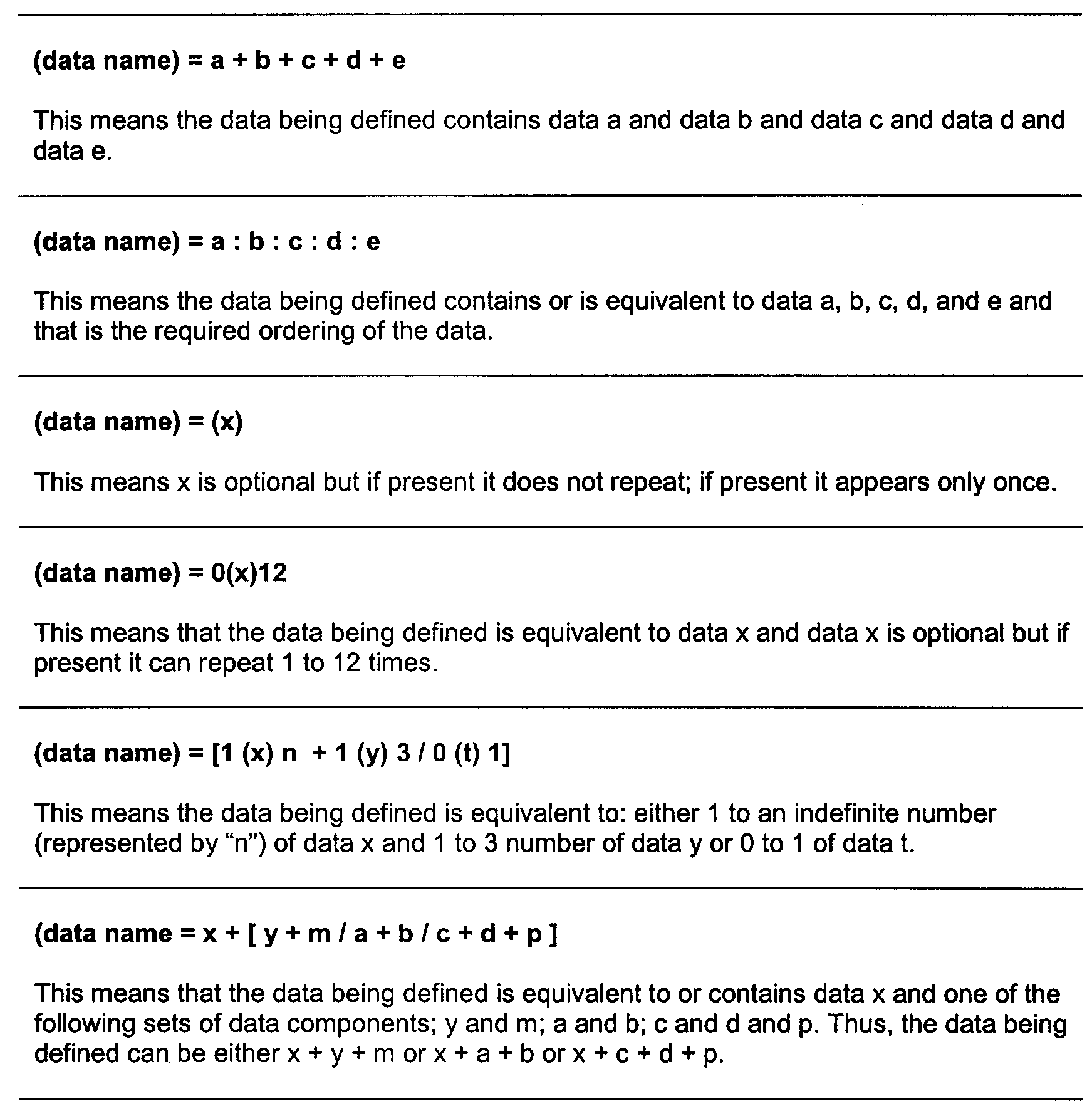
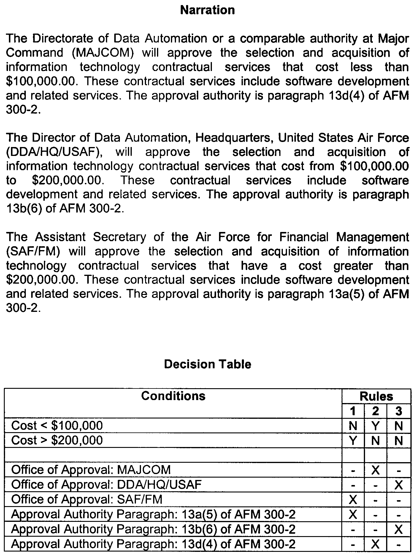
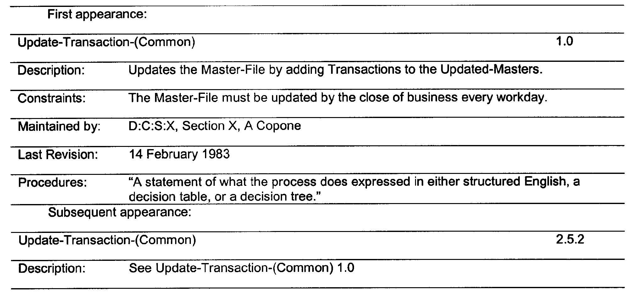
| Acronyms | Terms |
|---|---|
| ACIO | Acting Chief Information Officer |
| ACIO AD | Associate Chief Information Officer, Application Development |
| AD | Application Development |
| ASQ | Application Support & Quality |
| BI | Business Intelligence |
| CIM | Common Information Model |
| BPMN | Business Process Modeling Notation |
| CMK | Customer Managed Keys |
| DAX | Data Analysis Expression |
| DaaS | Data as a Service |
| DBMS | Database Management System |
| DCOS | Deputy Commissioner, Operation Support |
| DFD | Data Flow Diagrams |
| DMQA | Delivery Management & Quality Assurance |
| EA | Enterprise Architecture |
| ELC | Enterprise Life Cycle |
| FISMA | Federal Information Security Modernization Act of 2014 |
| FSP | Functional Specification Package |
| IAM | Identity & Access Management |
| iOS | Internet Operating System |
| ISS | Integrated Solutions Section |
| JAD | Joint Application Deployment |
| OMB | The Office of Management and Budget |
| OMG | Object Management Group |
| MDA | Model Driven Architecture |
| SA/SD | System Analysis/System Development |
| RAD | Rapid Application Deployment |
| RTO | Return On Investment |
| RTC | Rational Team Concert |
| REPO | Requirements Engineering Process Office |
| SDLC | Software Development Life Cycle |
| TIGTA | Treasury Inspector General Tax Administration |
| TOM | Tabular Object Model |
| UCA | Utility Communications Association |
| UI | User Interface |
| UML | Unified Modeling Language |
| Terms | Definitions |
|---|---|
| CIM Users Group | A subgroup of the Utility Communications Association International Users Group established to provide a forum in which users, consultants, and suppliers can cooperate and leverage the IEC CIM international standards to advance interoperability between utility enterprise system. |
| Business Process Modeling Notation | Provides a graphical notation for creating business processes in a Business Process Diagram, based on a flowcharting technique similar to UML. |
| Bubble Chart | Bubble charts are graphs used to compare the relationships between data objects in three numeric-data dimensions: the X-axis data, the Y-axis data, and data represented by the bubble size. Bubble charts are similar to XY scatter graphs. |
| Constraints | Restrictions or limitations on possible solutions. |
| System Designer | A person who creates a detailed design documentation for the development and integration of the computer systems. |
| Object Management Group | This is an international nonprofit technology and industry standards consortium. The mission of OMG is to establish and revise technology standards that provide real-world value for international end-users, vendors, government agencies, universities, and research institutions as needed. |
| Requirements Engineering Process Office | The Requirements Engineering Program Office (REPO) of Business Planning and Risk Management (BPRM) is the IRS authority on providing standards and guidance to Requirements Engineering activities, process modeling, and requirements-related solutions. |
| Rational Team Concert (IBM Engineering Workflow Management) | Formerly (RTC) IBM Engineering Workflow Management is a collaborative software development tool that teams use to manage all aspects of their work, such as iteration and release planning, change management, defect tracking, source control, and build automation. |
| Schema | The organization or structure for a database. |
| System Analyst | A person who uses analysis and design techniques to solve business problems using information technology. |
| Unified Modeling Language | Industry-standardized modeling language or collection of modeling techniques for visualizing, creating, and documenting artifacts of a system’s process. |