- 2.120.8 Interface Design Process
- 2.120.8.1 Program Scope and Objectives
- 2.120.8.1.1 Background
- 2.120.8.1.1.1 Process Description
- 2.120.8.1.1.2 Goal
- 2.120.8.1.1.3 Objectives
- 2.120.8.1.2 Authority
- 2.120.8.1.3 Roles and Responsibilities
- 2.120.8.1.4 Program Management and Review
- 2.120.8.1.5 Program Control
- 2.120.8.1.5.1 Control
- 2.120.8.1.5.2 Metrics
- 2.120.8.1.5.3 Tailoring Guidelines
- 2.120.8.1.5.4 Quality Assurance
- 2.120.8.1.6 Terms/Definitions/Acronyms
- 2.120.8.1.6.1 Terms and Definitions
- 2.120.8.1.6.2 Acronyms
- 2.120.8.1.7 Related Resources
- 2.120.8.1.8 Training
- 2.120.8.1.1 Background
- 2.120.8.2 Process Workflow
- 2.120.8.2.1 Main Process Diagram
- 2.120.8.2.2 Inputs
- 2.120.8.2.3 Outputs
- 2.120.8.2.4 Activities
- 2.120.8.2.5 Procedure
- 2.120.8.2.5.1 ID 1.0: Define Interface Criteria
- 2.120.8.2.5.1.1 Cross-Functional Flow Diagram
- 2.120.8.2.5.2 ID 2.0: Identify The Systems or Components being Interfaced
- 2.120.8.2.5.2.1 Cross-Functional Flow Diagram
- 2.120.8.2.5.3 ID 3.0: Develop Alternative Interface Designs and Selection Criteria & Select Interface Design
- 2.120.8.2.5.3.1 Cross-Functional Flow Diagram
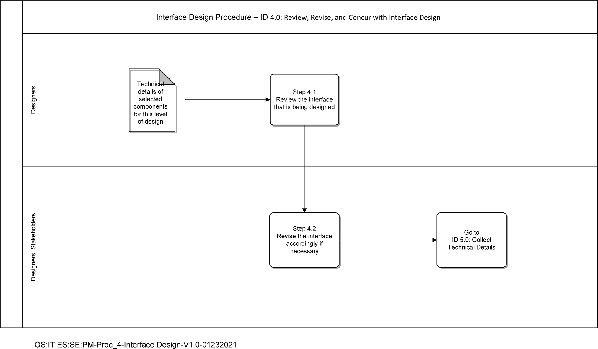
- 2.120.8.2.5.4 ID 4.0: Review, Revise, and Concur with Interfaces Design
- 2.120.8.2.5.4.1 Cross-Functional Flow Diagram
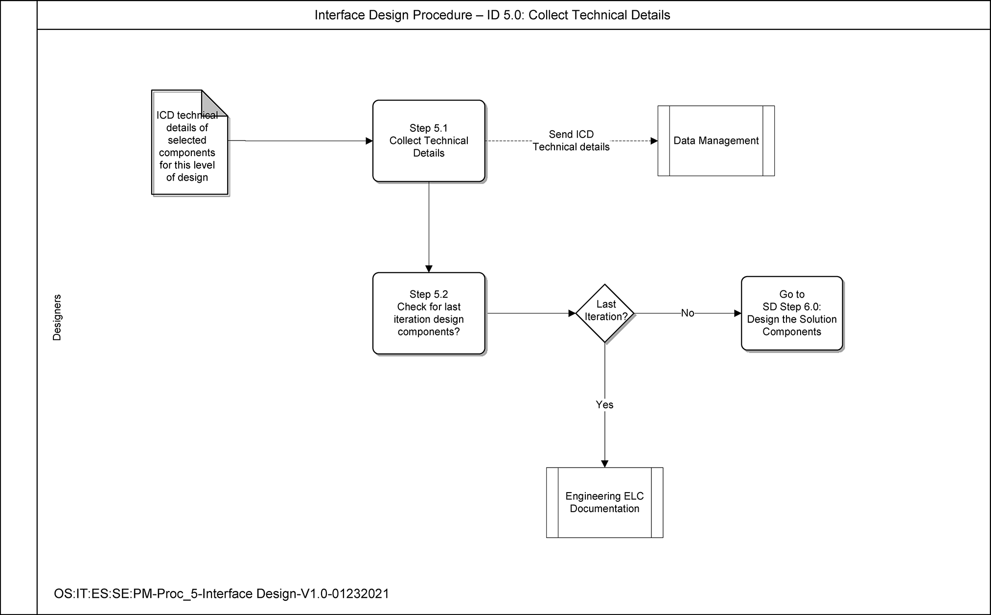
- 2.120.8.2.5.5 ID 5.0 Collect Technical Details
- 2.120.8.2.5.5.1 Cross-Functional Diagram
- 2.120.8.2.5.1 ID 1.0: Define Interface Criteria
- 2.120.8.1 Program Scope and Objectives
Part 2. Information Technology
Chapter 120. Engineering
Section 8. Interface Design Process
2.120.8 Interface Design Process
Manual Transmittal
May 29, 2024
Purpose
(1) This transmits revises IRM 2.120.8 Solution Engineering - Interface Design Process Description (PD) and Procedure dated January 12, 2023 due to be OneSDLC Compliant.
Material Changes
(1) Making changes to IRM to be OneSDLC Compliant.
Effect on Other Documents
IRM 2.120.8 Interface Design Process dated January 12, 2023 is superceded. .Audience
This process description is applicable to all Information Technology (IT) organizations, contractors, and other stakeholders having responsibility for developing IT systems.Effective Date
(05-29-2024)
Rajiv Uppal
Chief Information Officer
-
Overview -This IRM describes the formal process for implementing the requirements of the Interface Design process.
-
Purpose -This IRM contains procedural steps for System Designers to successfully select and design interfaces to requirements.
-
Audience - These procedures apply to IRS Information Technology (IT) employees and contractors who are responsible for selecting and designing computer system.
-
Policy Owner - Associate Chief Information Officer (ACIO), Enterprise Services, is responsible for overseeing all aspects of our systems that operate the nation’s tax infrastructure.
-
Program Owner - Solution Engineering division (SE), which is under Information Technology, Enterprise Services (ES).
-
Primary Stakeholders - Application Development (AD), Cybersecurity, Enterprise Operations (Eops), Solution Engineering (SE), Enterprise Architecture (EA), User and Network Services (UNS)
-
Program Goals - This IRM provides the fundamental knowledge and procedural guidance for those who design and implement computer systems.
-
A process is defined as “A set of related activities that accomplish a common goal”. The process definition laid out in this document further breaks down these Activities into Tasks, each of which have a complete set of attributes defined such as data and tool specifications and the role(s) responsible for executing the tasks. The document also includes process goal and objectives, metrics, role definitions, policies and other process related attributes.
-
This Interface Design process description describes what happens within the Interface Design process and provides an operational definition of the major components of the process. This description specifies, in a complete, precise, and verifiable manner, the requirements, design, and behavior characteristics of the Interface Design process.
-
The process goal describes a specific purpose or achievement toward which the efforts of the process are directed. Each process has a specific focus and when combined with the other processes, forms a comprehensive framework for delivering and managing services.
-
Interface is selected from alternative designs
-
Interface designs are developed
-
-
All proposed changes to this document must be submitted in writing, with supporting rationale, to the Solution Engineering division.
-
Each process defines at least one role. Each role is assigned to perform specific tasks within the process. The responsibilities of a role are confined to the specific process. They do not imply any functional standing within the hierarchy of an organization. For example, the process manager role does not imply the role is associated with or fulfilled by someone with functional management responsibilities within the organization. Within a specific process, there can be more than one individual associated with a specific role. Additionally, a single individual can assume more than one role within the process although typically not at the same time.
Name Description Designers -
Define interface criteria
-
Identification of component interfaces both internal and external
-
Ensuring all interface standards are followed
-
Ensuring interface requirements are allocated to components and sub-components levels
-
Developing all required technical interface details at solution level for ICD
-
Evaluate the interface alternative designs against criteria
Stakeholders -
These are the specific people or groups who have a stake, or an interest, in the outcome of the project
-
-
Policies outline a set of plans or courses of action that are intended to influence and determine decisions or actions of a process. Policies provide an element of governance over the process that provides alignment to business vision, mission and goals.
Process Management Statement: The Interface Design process will have a single Process Owner and a separate Process Manager, responsible for implementation and ensuring adherence to the process. The process will be reviewed regularly to ensure that it continues to support the business requirements of the enterprise. The process will be designed and developed based on ROI to the business. Process metrics will be focused on providing relevant information as opposed to merely presenting raw data. People: Statement: Roles and responsibilities for the process must be clearly defined and appropriately staffed with people having the required skills and training. The mission, goals, scope and importance of the process must be clearly and regularly communicated by upper management to the staff and business customers of IT. All IT staff (direct and indirect users of the process) shall be trained at the appropriate level to enable them to support the process. Rationale: It is imperative that people working in, supporting or interacting with the process in any manner understand what they are supposed to do. Without that understanding Interface Design process will not be successful. Process: Statement: Modifications to the Interface Design process must be approved by the Process Owner. The design of the process must include appropriate interfaces with other processes to facilitate data sharing, escalation and workflow. The process must be capable of providing data to support real-time requirements as well as historical/trending data for overall process improvement initiatives. The process must be fully documented, published and accessible to the various stakeholders of the process. The process will be reviewed on a periodic basis in order to ensure it continues to support organizational goals and objectives (continuous improvement). The process must include Inputs, Outputs, Controls, Metrics, Activities, Tasks, Roles and Responsibilities, Tool and Data requirements along with documented process flows. The process will be kept straight forward, rational, and easy to understand. Rationale: The process must meet operational and business requirements. Technology and Tools: Statement: All tools selected must conform to the Enterprise Architectural Standards and direction. Existing in-house tools and technology will be used wherever possible, new tools will only be entertained if they satisfy a business need that cannot be met by current in-house tools. The selection of supporting tools must be process driven and based on the requirements of the business. Selected tools must provide ease of deployment, customizing and use. Automated workflow, notification and escalation will be deployed wherever possible to minimize delays, ensure consistency, reduce manual intervention and ensure appropriate parties are made aware of issues requiring their attention. . Rationale: Technology and tools should be used to augment the process capabilities, not become an end themselves.
-
Activities involved in ensuring a process is predictable, stable, and consistently operating at the target level of performance.
-
Process controls represent the policies and guiding principles on how the process will operate. Controls provide direction over the operation of processes and define constraints or boundaries within which the process must operate.
Name Description Solution Engineering Policy (Directive) The project will include in its engineering plan either by inclusion or reference, planning materials specifying how the following will be accomplished: -
Execution Engineering Process
-
Obtaining needed resources to perform Engineering Process
-
Control of work products required by the Management Process
-
Engagement of stakeholders affected by the Interface Design Process
-
Monitoring and Controlling of the Management Process
-
Collection of Management Process measures
-
Review of Management Process status with high level of management
-
Establishment of the Management Process within the project's defined processes
-
Submission of lesson learned and process improvement suggestions from the execution of Management Process.
-
Recency of signature (every 3 years)
-
Annual reviews
Scope All projects will follow the Interface Design process which will be used to perform interface designs to requirements and associated activities in accordance with this policy. -
-
Metrics are used for the quantitative and periodic assessment of a process. They should be associated with targets that are set based on specific business objectives. Metrics provide information related to the goals and objectives of a process and are used to take corrective action when desired results are not being achieved and can be used to drive continual improvement of process effectiveness and efficiency.
-
Management will regularly set targets for process performance, gather quantifiable data related to different functions of the Interface Design process, and review that data in order to make informed decisions and take appropriate corrective action, if necessary. All Measurements will have a defined data dictionary, map to the organizational strategic goals, and be documented in a Process Measurement Plan. The Process Measurement Plan template is available in the IT PAL.
-
The tailoring guidelines identify the allowable variations of the IT organization’s standard process as needed for adjustments (adding, deleting, modifying) relative to specific operational or functional needs of another organization. Process tailoring is about roles and procedures, not the standard process or major activities defined in this process. All tailoring request, with supporting rationale, must be submitted in writing to and approved by the Interface design Process owner.
-
Step 1: “Define Interface Criteria” may be tailored out when a project is a maintenance project whose design is dictated by the existing system or the design of the system is fully constrained by the Enterprise Architecture.
-
Step 2: “Identify the Systems or Components” being Interfaced may be tailored out when a project is a maintenance project whose design is dictated by the existing system or the design of the system is fully constrained by the Enterprise Architecture.
-
Step 3: “Development Alternative Interface Designs and Selection Criteria & Select Interface Design” may be tailored out when a project is a maintenance project whose design is dictated by the existing system or the design of the system is fully constrained by the Enterprise Architecture.
-
Step 4: “Review, Revise, and Concur with Interfaces Design” may be tailored out when a project is a maintenance project whose design is dictated by the existing system or the design of the system is fully constrained by the Enterprise Architecture.
-
Step 5: “Collect Technical Details” may be tailored when the project is a maintenance project whose design is dictated by the existing system, no significant change is made to the systems logical design, and approved equivalent documentation exists. Updates to the equivalent documentation may be substituted and the activities modified as needed to support the updating of the documentation. The list of approved equivalent documentation is available on the IPM PAL. If the work product Documented Interfaces, Evaluations, and Rationale is tailored out, references to existing requirements and traceability matrixes must be substituted.
-
Terms/Definitions/Acronyms
-
Terms and Definitions
Term Definition Customer requirement The result of eliciting, consolidating, and resolving conflicts among the needs, expectations, constraints, and interfaces of the product’s relevant stakeholders in a way that is acceptable to the customer. Interface Design process The process is used to specify steps and procedural tasks that all IT projects need to accomplish to conduct their interface designs. RACI The RACI model is based on the principle that people act in one of four ways when executing a task. It accounts for the fact that more than one role may be active in performing a specific task while clearly defining specific responsibilities for that role. While many roles may be involved in a task only one is Accountable for the results. “The actions are: R Responsible for the action (may do the task) A Accountable for the action (including approval) C Required to be Consulted on the action I Required to be Informed of the action If a task does not have an Accountable role indicated then the Responsible role is assumed to be accountable for the task.”
-
Acronyms
Acronyms Definition COTS Commercial Off The Shelf ES Enterprise Services ICD Interface Control Document IPM Integrated Process Management IRM Internal Revenue Manual IRS Internal Revenue Service ID Interface Design IT Information Technology OneSLDC One Solution Delivery Lifecycle PAL Process Asset Library PD Process Description PMI Project Management Institute QA Quality Assurance RACI Responsible, Accountable, Consulted and Informed SDSR Simplified Design Specification Report SE Solution Engineering SEPM Solution Engineering Process Maturity
-
Process training involves training all stakeholders about key processes that are crucial for an organization to deliver business objectives. Training provides clarity to employees on a set of procedures that needs to be carried out as part of the process and the best possible way to do them. List below the training resources available for this process:
-
Interface Design process training class
-
-
A process workflow consists of Activities and Tasks, Inputs and Outputs, Roles, and Flow Diagrams. It describes the tasks, procedural steps, organizations or people involved, required input and output information, and tools needed for each step of the process.
-
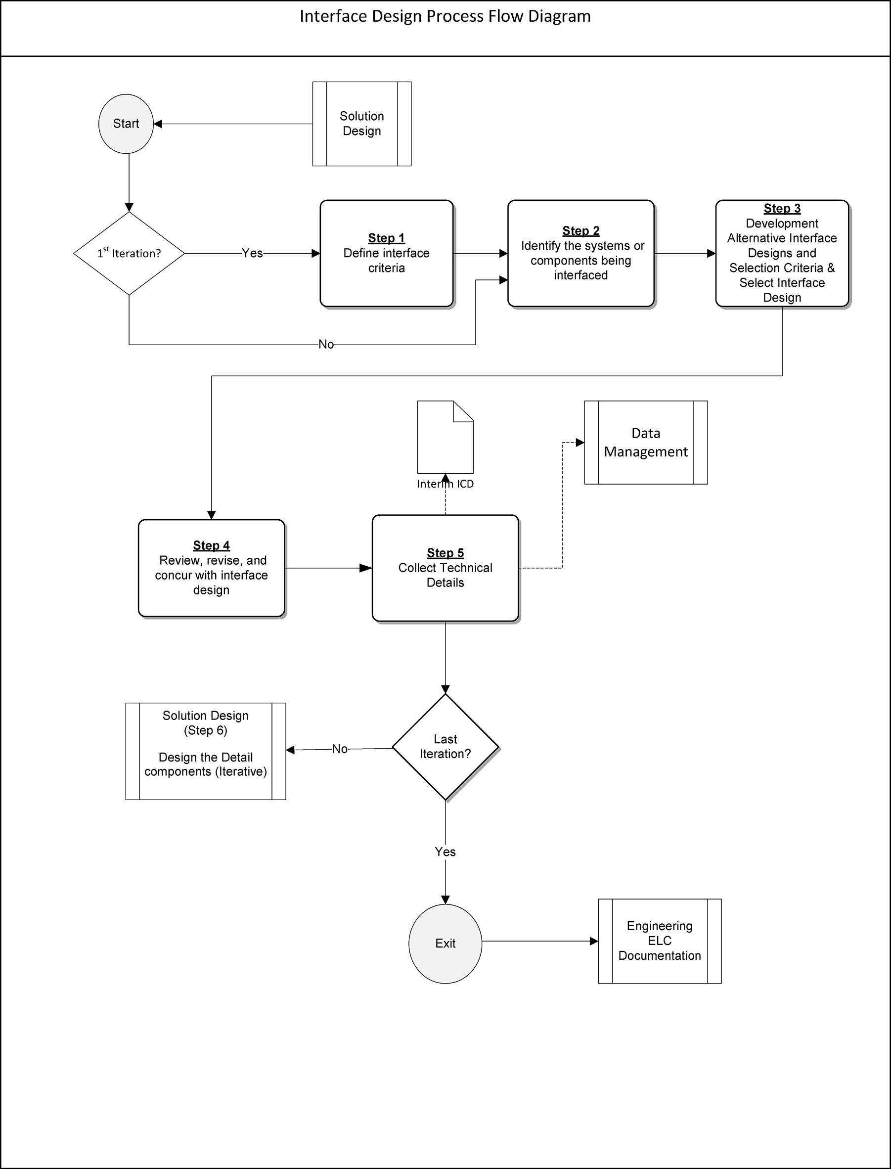
Interface Design Process Diagram
-
Process inputs are used as triggers to initiate the process and to produce the desired outputs. Users, stakeholders or other processes provide inputs. The following is a list of inputs for this process:
Name Description Supplier Approved System Requirements System requirements are used in determining what the solution to be implemented is required to do. BSR (Business System Report), VSA (Vision, Scope, and Architecture) for Agile Allocated Customer Requirements Allocated requirements are used to give context to the system requirements. BSR, VSA Operation Concept Concept of operation is used to give context to the system and allocated customer requirements Solution Concept, BSR, VSA Functional Architecture Functional architecture is used to give context to the system requirements BSR, VSA Design Specification SDSR is used to give context for the interface design to the system and allocated customer requirements SDSR Design Constraints Constraints are used to limit design and implementation alternatives Solution Engineering Software Engineering Practice Group
-
Each process produces tangible outputs. These outputs can take the form of products or data and can be delivered to a user or stakeholder, or, they can be used as inputs to other processes. Outputs are measurable in terms of quantity and quality.
Name Description Recipient Technical Details Technical Detail will document the followings: -
Alternative interface screening criteria
-
Alternative interfaces
-
Selection criteria for final selection
-
Documented design solutions, evaluations, and rationale for selected interface design
Engineering Documentation Process -
-
An activity is a major unit of work to be completed in achieving the objectives of the process. A process consists of a sequence of related activities that transforms inputs into outputs and performed by the roles defined in the process. Identify the activities in the process and provide a brief description. The activities must correspond with the high-level process flow diagram above.
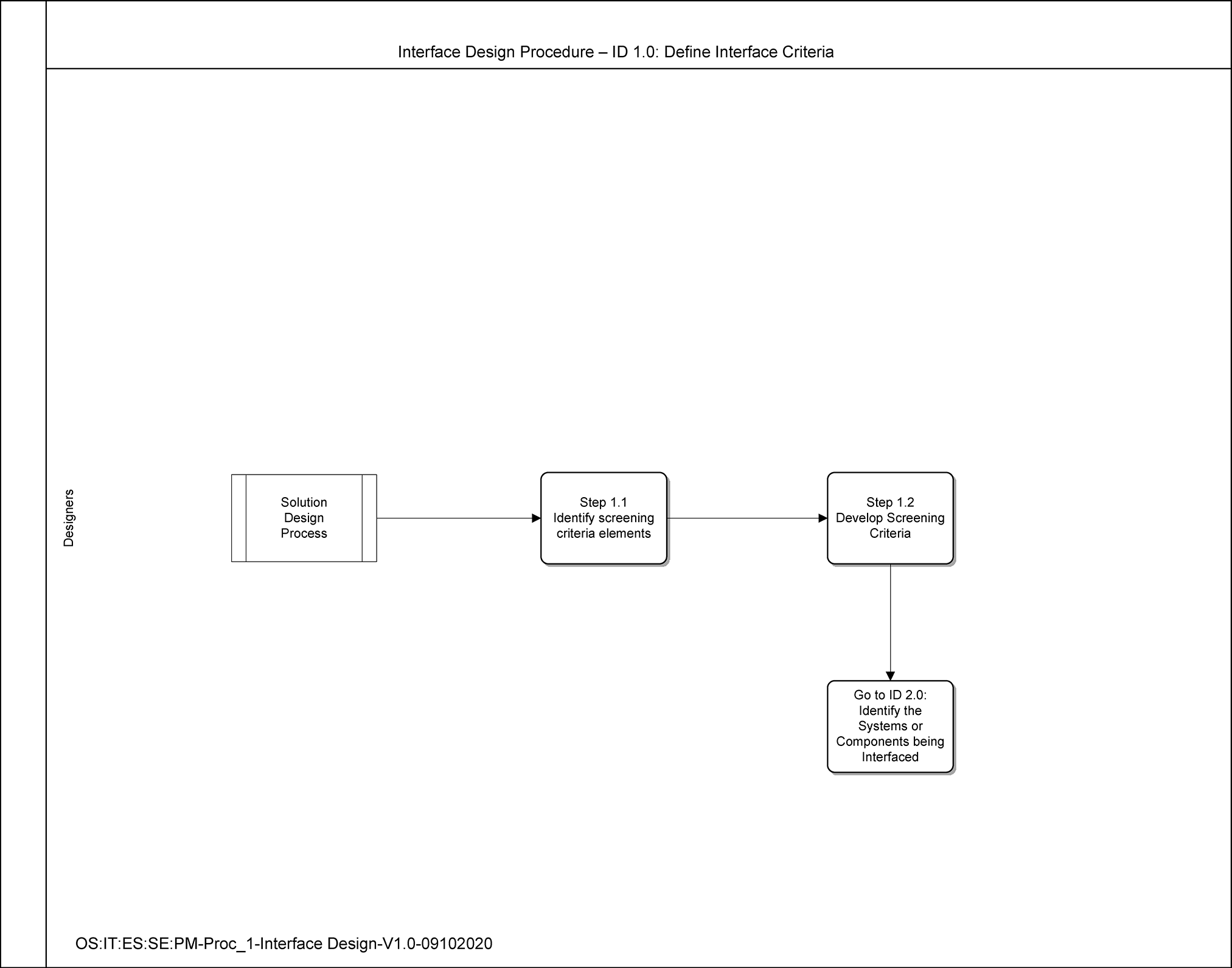
ID Name Description ID 1.0 Define Interface Criteria To define screening criteria to select set of alternative interfaces for consideration -
Identify screening criteria elements
-
Develop screening criteria to select a set of alternative interfaces for consideration
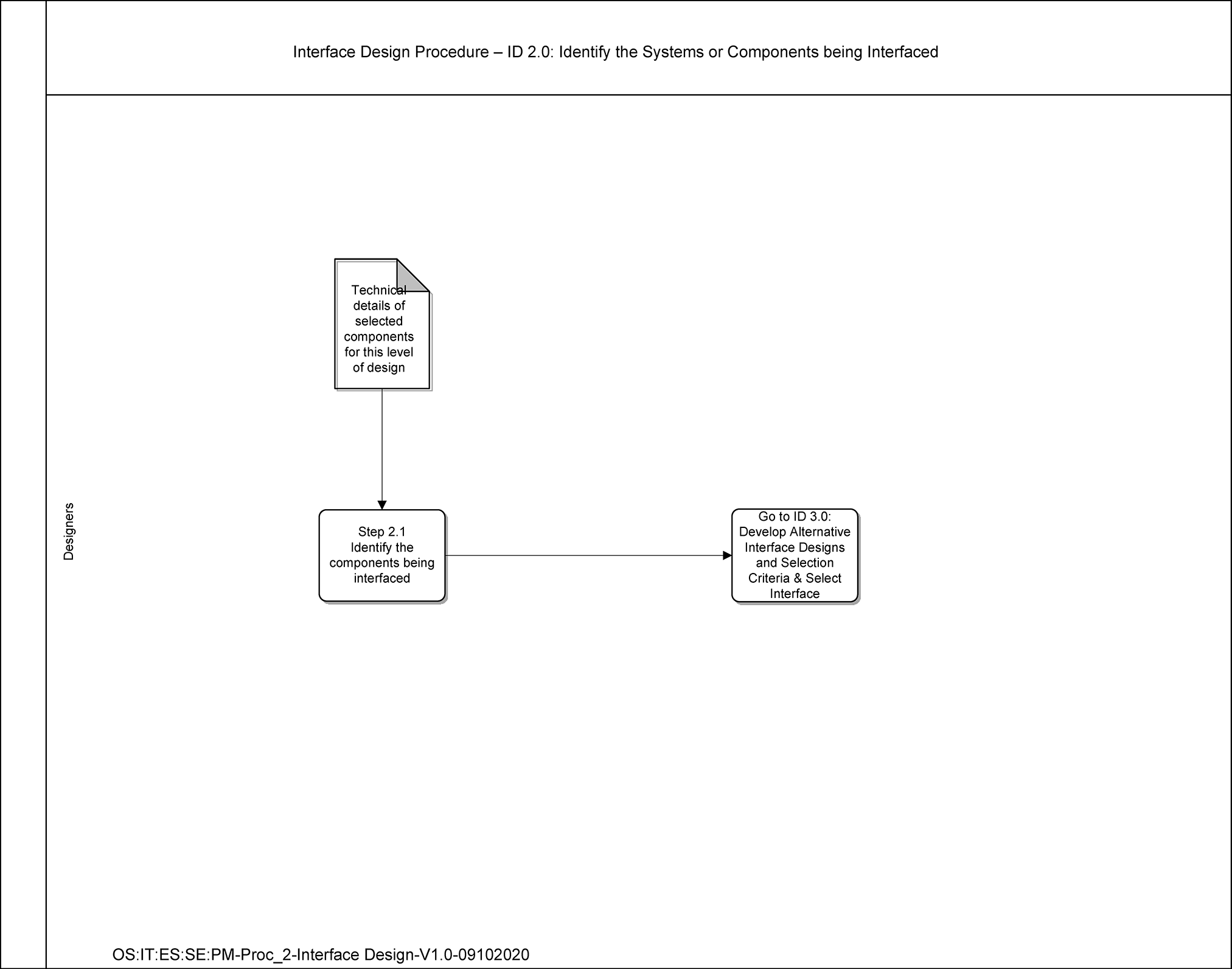
ID 2.0 Identify the Systems or Components being Interfaced To identify the components or sub-components being interfaced. -
Identify the components being interfaced
-
Identify the sub-components interfaced
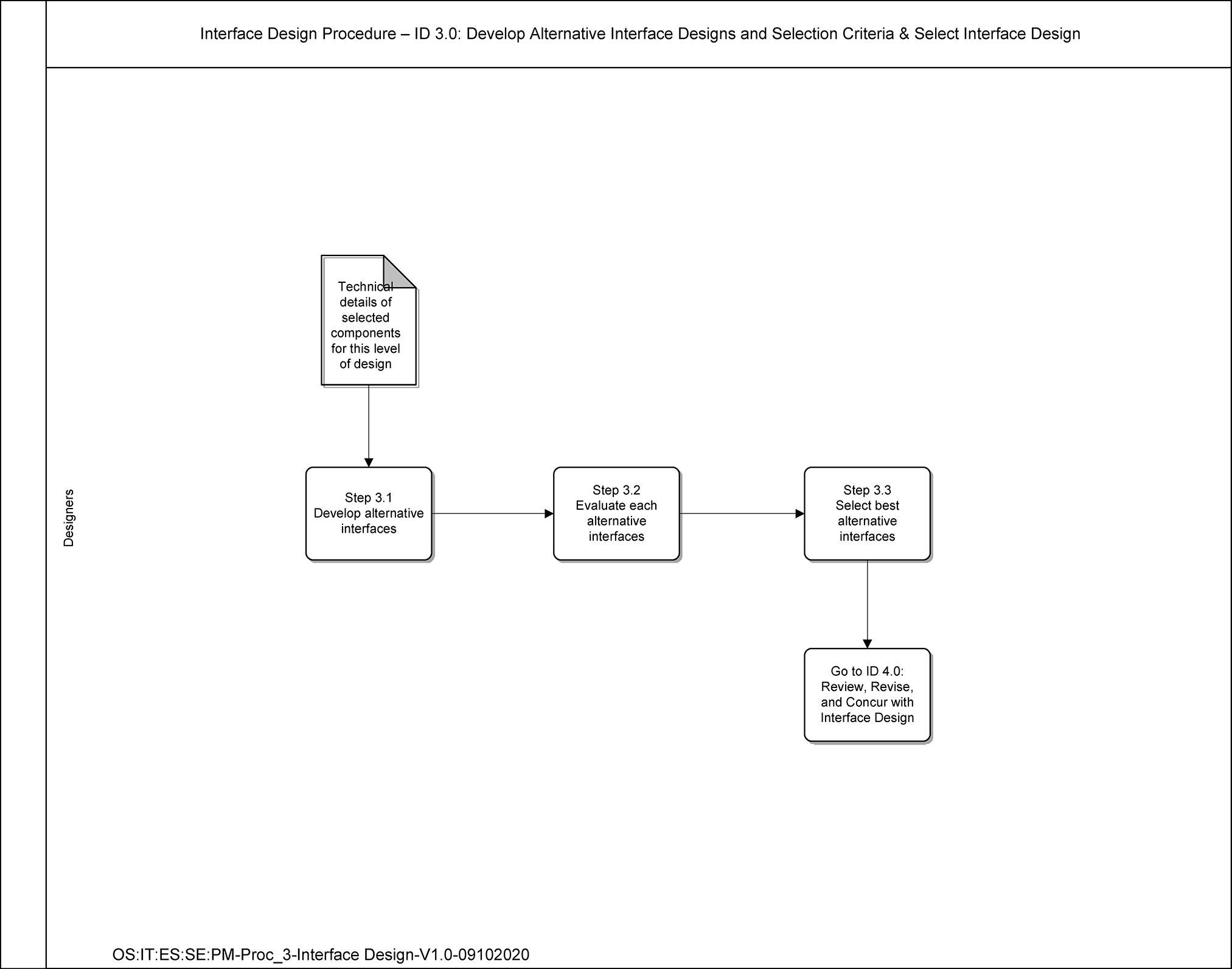
ID 3.0 Develop Alternative Interface Designs and Selection Criteria & Select Interface Design To develop, evaluate and select solution. -
Develop alternative interfaces
-
Evaluate each alternative interfaces
-
Select the best alternative interface
ID 4.0 Review, Revise, and Concur with Interfaces Design To review the interface that is being designed. -
Review the interface that is being designed
-
Revise the interface accordingly if necessary
ID 5.0 Collect Technical Details To collect all technical details: -
Collect the selected interface design
-
Collect the rationale for the interface selection
-
Collect internal and external interface information
-
Send ICD technical data to “Data Management” process
-
Check whether all interfaces are being designed
-
If yes, go to “Engineering Documentation” process
-
If no, design the interfaces for the next level of design components by going to the process, SD Step 6.0 “Design the Solution Components”
-
-
-
A procedure provides the step by step instructions, or tasks, in how to perform each activity in the process and usually applies to a single role that will be responsible in performing the task.
-
This step is to define interface criteria that meet interface requirements
ID Task Name and Description Role RACI* Duties ID 1.1 Identify screening criteria elements
Screening criteria are used to narrow down the list of alternatives to those consistent with interface requirementsDesigners RA -
Consider following criteria:
-
Scope
-
Constraints (Design, Cost, Risk)
-
Alternative solution impact on current IT operations
-
Alternative solution impact on End Users
ID 1.2 Develop screening criteria to select a set of alternative interfaces for consideration
This task is to develop screening criteria to narrow down the list of interface alternativesDesigners RA -
Develop screening criteria consistent with the interface requirements
Note:
*RACI is a responsibility matrix that describes the participation by various roles in completing the tasks or deliverable for a project or business process. RACI is derived from the four key responsibilities typically used:
-
Responsible – The person that is assigned to do the work.
-
Accountable – The person that makes the final decision and has ultimate ownership.
-
Consulted – The person that must be consulted before a decision or action is taken.
-
Informed – The person that must be informed that a decision or action has been taken.
-
-
This step is to define criteria to select the solution
ID Task Name and Description Role RACI* Duties ID 2.1 Identify the components being interfaced
Identify the components or sub-components being interfacedDesigners RA -
Identify the components or sub-components being interfaced
Note:
*RACI is a responsibility matrix that describes the participation by various roles in completing the tasks or deliverable for a project or business process. RACI is derived from the four key responsibilities typically used:
-
Responsible – The person that is assigned to do the work.
-
Accountable – The person that makes the final decision and has ultimate ownership.
-
Consulted – The person that must be consulted before a decision or action is taken.
-
Informed – The person that must be informed that a decision or action has been taken.
-
-
This step is to evaluate and select Solution
ID Task Name and Description Role RACI* Duties ID 3.1 Develop alternative interfaces
Develop alternative interfaces to be consideredDesigners RA -
Consider design constraints
-
Examine existing interfaces
-
Develop interface design alternatives (3 alternatives for consideration are preferred)
-
Reuse and design constraints may limit design options
-
Ensure all alternatives meet interface requirements
ID 3.2 Evaluate each alternative interfaces
Evaluate each interface alternative against the selection criteriaDesigners RA -
Evaluate each interface alternative against the established selection criteria
-
Score using criteria and associated weights
ID 3.3 Select the best alternative interface
Select the best alternative interface that satisfy the established selection criteriaDesigners RA -
Select the best alternative interface that satisfy the established selection criteria
-
Document results
Note:
*RACI is a responsibility matrix that describes the participation by various roles in completing the tasks or deliverable for a project or business process. RACI is derived from the four key responsibilities typically used:
-
Responsible – The person that is assigned to do the work.
-
Accountable – The person that makes the final decision and has ultimate ownership.
-
Consulted – The person that must be consulted before a decision or action is taken.
-
Informed – The person that must be informed that a decision or action has been taken.
-
-
This step is to ensure that components and design patterns are reused when appropriate and ensures that reuse of components and design patterns conform to organization and project policy
ID Task Name and Description Role RACI* Duties ID 4.1 Review the interface that is being designed
Review the designed interface for meeting required interface requirements and correctnessStakeholders RAI -
Review to validate interface requirements are being met.
-
Review the correctness for technical details
ID 4.2 Revise the interface accordingly if necessary
Update the interface if revision is necessaryDesigners RA -
Revise the interface accordingly if necessary
Note:
*RACI is a responsibility matrix that describes the participation by various roles in completing the tasks or deliverable for a project or business process. RACI is derived from the four key responsibilities typically used:
-
Responsible – The person that is assigned to do the work.
-
Accountable – The person that makes the final decision and has ultimate ownership.
-
Consulted – The person that must be consulted before a decision or action is taken.
-
Informed – The person that must be informed that a decision or action has been taken.
-
-
To collect all documentation into a single package and to determine the level of detail to be retained.
ID Task Name and Description Role RACI* Duties ID 5.1 Collect Technical Details
Collect all technical detailsDesigners RA -
Evaluation reports of selected new technologies
-
Evaluation reports of selected COTS products
-
Solution component selection decisions and rationale
-
Documented relationships between requirements and selected solution components
-
Documented solutions, evaluations, and rationale
-
Solution architecture
-
Solution component designs
-
Criteria for design and solution component reuse
-
Make-or-buy analyses
-
Guidelines for choosing COTS solution components
-
Send ICD technical data to “Data Management” process
ID 5.2 Check for “Last iteration”
Check for last iteration design components are being designedDesigners RA -
Check for the last iteration design components are being designed
-
If yes, go to “Engineering Documentation” process
-
If no, design the next level of design components by going to SD Step 6.0 “Design the Solution Components”
-
Note:
*RACI is a responsibility matrix that describes the participation by various roles in completing the tasks or deliverable for a project or business process. RACI is derived from the four key responsibilities typically used:
-
Responsible – The person that is assigned to do the work.
-
Accountable – The person that makes the final decision and has ultimate ownership.
-
Consulted – The person that must be consulted before a decision or action is taken.
-
Informed – The person that must be informed that a decision or action has been taken.
-

 )
or https:// means you've safely connected to the .gov website. Share sensitive information only on official, secure websites.

