
 )
or https:// means you've safely connected to the .gov website. Share sensitive information only on official, secure websites.
)
or https:// means you've safely connected to the .gov website. Share sensitive information only on official, secure websites.
- 2.5.12 Design Techniques and Deliverables
- 2.5.12.1 Program Scope and Objectives
- 2.5.12.1.1 Background
- 2.5.12.1.2 Authority
- 2.5.12.1.3 Roles and Responsibilities
- 2.5.12.1.4 Program Management and Review
- 2.5.12.1.5 Acronyms/Terms
- 2.5.12.1.6 Terms/Definitions
- 2.5.12.1.7 Related Resources
- 2.5.12.2 System and Software Developer’s Best Practice Overview
- 2.5.12.3 Software Design
- 2.5.12.3.1 Design Characteristics
- 2.5.12.3.2 Software Design and Structure
- 2.5.12.3.2.1 Software Design Levels
- 2.5.12.3.3 Software Modeling
- 2.5.12.3.4 Software Design Refinement Principles
- 2.5.12.3.5 Heuristic Evaluation
- 2.5.12.3.6 Modular Decomposition
- 2.5.12.3.7 Software Design Patterns Overview
- 2.5.12.3.8 Software Design Patterns - Best Practices for Developers
- 2.5.12.3.9 Object-Oriented Analysis and Design Process
- 2.5.12.3.9.1 Use Case Diagrams
- 2.5.12.4 User Interface (UI) Design Principles
- 2.5.12.4.1 User Interface Design Process
- 2.5.12.4.2 Design Wireframes and Mock-ups
- 2.5.12.4.2.1 Prototype Design Best Practices
- 2.5.12.4.2.2 Prototyping Benefits Throughout the Enterprise Life Cycle (ELC)
- 2.5.12.5 Structure Chart Overview
- 2.5.12.5.1 Structure Chart Best Practices
- 2.5.12.5.2 Transform Analysis/Transaction Analysis Overview
- 2.5.12.5.2.1 Transform Analysis Best Practices
- 2.5.12.5.2.2 Transaction Analysis Best Practices
- 2.5.12.5.2.3 Information Specification
- 2.5.12.5.2.4 Structure Chart Refinement
- 2.5.12.6 Structure Chart Conventions and Standards
- 2.5.12.6.1 Module Numbering
- 2.5.12.6.1.1 Multiple Page Structure Charts
- 2.5.12.6.1.2 Pre-existing (Common) Modules
- 2.5.12.6.2 Module Notations
- 2.5.12.6.2.1 Special Module Call Notation
- 2.5.12.6.2.2 Lexical Inclusion
- 2.5.12.6.2.3 Pre-Existing Module Notation
- 2.5.12.6.2.4 File Notation
- 2.5.12.6.3 Structure Chart Common Environment
- 2.5.12.6.4 Structure Chart Interface Parameters (Couples)
- 2.5.12.6.4.1 Interface Parameter Names
- 2.5.12.6.4.2 Identifying Data and Control Parameters
- 2.5.12.6.5 Sorts
- 2.5.12.6.6 Analysis/Design Cross-Reference List
- 2.5.12.6.1 Module Numbering
- 2.5.12.7 Structure Chart Module Specification
- 2.5.12.7.1 Pseudocode
- 2.5.12.7.1.1 Pseudocode Best Practices
- 2.5.12.7.2 Module Specification Development/Standards
- 2.5.12.7.3 Pseudocode-Conventions/Standards
- 2.5.12.7.3.1 Reusable (Common) Modules
- 2.5.12.7.3.2 Organization and Maintenance
- 2.5.12.7.1 Pseudocode
- 2.5.12.8 Structure Charts Packaging and Preprogramming Considerations
- 2.5.12.9 Structured Design/Programming Interface - Structure Charts
- 2.5.12.10 Software Release/Maintenance/Evolution
- Exhibit 2.5.12-1 Example of a Structure Chart
- Exhibit 2.5.12-2 Example of Page 1 of a Structure Chart using a Parameter Table
- Exhibit 2.5.12-3 Contents and Format of Analysis/Design Cross-Reference List
- Exhibit 2.5.12-4 Acronym/Terms
- Exhibit 2.5.12-5 Terms/Definitions
- 2.5.12.1 Program Scope and Objectives
Part 2. Information Technology
Chapter 5. Systems Development
Section 12. Design Techniques and Deliverables
2.5.12 Design Techniques and Deliverables
Manual Transmittal
December 16, 2021
Purpose
(1) This transmits revised Internal Revenue Manual (IRM) 2.5.12, Systems Development, Design Techniques and Deliverables. This IRM was developed to describe techniques for analyzing, designing, and modeling system development software designs.
Material Changes
(1) Manual Transmittal signature, changed the title from Acting, Chief Information Officer signature to Chief Information Officer for Nancy A. Sieger.
(2) 2.5.12.1.3 (7), Updated the role and responsibilities of the Customer Service Director
(3) 2.5.12.1.7, Added resource “The Gang of Four (GoF) Design Patterns Reference. Learning Object-Oriented Design & Programming Version 2.0, January 10, 2017
(4) 2.5.12.2, Added System and Software Developer’s Best Practice Overview
(5) 2.5.12.2 (1), Added IRS system development and software development teams have many responsibilities, for example:
-
Gathering requirements from stakeholders
-
Analyze, implement current and future system and software programs
-
Mitigate risks for future product changes
-
Implementing and updating Enterprise Life Cycle documentation (artifacts)
-
Creating design and test plans
-
Establishing the design and deployment of enhancements to the current IRS architecture
-
Perform maintenance procedures for software programs
(6) 2.5.12.2.1, Added Enterprise Architecture (EA) Application Design Overview
(7) 2.5.12.2.1 (1), Added The goal of the application architecture section of the EA is to define a set of architectural patterns from which projects may select in order to build and deploy their applications in a manner that is consistent with the objectives of the IRS as an enterprise. Projects can choose from a limited set of application architecture patterns to build application systems.
(8) 2.5.12.2.1 (2), Added Projects are expected to develop their own design level approaches, and documentation based on the architecture guidelines provided in the Enterprise Architecture, included updated EA hyperlink
(9) 2.5.12.2.1 (9), Corrected the word "work flow" to "workflow"
(10) Added explanation During 1994 four authors: Eric Gamma, Richard Helm, Ralph Johnson and John Vlissides who are jointly known as the "Gang of Four " (GOF) published a book titled Design Patterns - Elements of Reusable Object-Oriented Software which started the concept of Design Pattern in Software Development. Design patterns provide an industry standard approach to solving recurring problems standard terminology and significance to each scenario
(11) 2.5.12.3.8 (1) (a - z) Added Software Design Patterns - Best Practices for Developers
(12) The best practices for developers using Design Patterns are as follows:
-
Behavioral Patterns (Chain of Responsibility) - Use this pattern when:
• You need to process a notification using a hierarchical chain of objects
• Not every observer is created equally -
For Chain of Responsibility Pattern implementation see
Chain of Responsibility Pattern Implementation
A Create an Interface for the chain which has the method needed. B Specific classes in the chain must implement the Interface and the specific classes constructor must set up the Interface successor value (private value). C Top of chain (last notified), has no successor defined D Each instance method defined must be set up to deal with whatever event might be specific to that class in the chain. E If it can’t handle it, it passes it along to the successor.method() F Last method in chain must be able to handle event (in a generic way if nothing else) -
Behavioral Patterns (Iterator) - Use this pattern when:
• You want to access the elements of a collection without having to know any internal details of the collection
• You are dealing with a collection of objects
• You are mixing collection types and need to access them in a standard way -
For Iterator Pattern implementation see Figure 2.5.12-6
Figure 2.5.12-1
Iterator Pattern Implementation
A Create a classIterator that implements Iterator -
Give the class a local variable to store what is in the collection (array, vector, etc)
-
Add a local variable to keep track of where you are in the collection
-
Add the following methods: "next" , "hasNext" , and "remove"
-
The method "hasNext" returns a Boolean (true if not at the end of the collection)
-
The method "next" returns the succeeding item from the collection
The method" remove" takes something out of the collection -
-
Behavioral Patterns (Observer) - Use this pattern when:
• You have a group that needs to know when something happens (the subject lets the observers know when something has happened)
• You need to send notifications to a series of objects
• You need to be able to modify who is observing at runtime -
For Observer Pattern implementation see Figure 2.5.12-6:
Figure 2.5.12-2
Observer Pattern Implementation
A. Create a Subject (what is to be observed) Interface -
registerObserver(Observer o)
-
removeObserver(Observer o)
-
notifyObserver(Observer o)
-
B. Create an Observer Interface -
receiveNotice()
C. Class to be watched implements the Subject Interface D. Class to do watching implements Observer Interface F. registerObserver puts Observers into a Vector (removeObserver takes them out) G. When code needs to notify Observers, loop through the vector and call the Observers receiveNotice() method (passing in whatever is needed/expected) -
-
Behavioral Patterns (Template) -
Use this pattern when:Note:
Defines the skeleton of an algorithm leaving some steps to subclasses; however, if every step needs to be customized then this pattern is pointless
• You have an algorithm that is made up of multiple steps, and you want to customize some of those steps
• If you have steps that are shared between various implementations of the algorithm -
For Template Pattern implementation do as follows:
• Define abstract class with final method that calls all steps (functions)
• Define default behavior for steps in abstract class (public methods, not necessarily final)
• Add conditions to steps if necessary
• Extend abstract class, override method for steps that are different -
Creational Patterns (Builder) -
Use this pattern when:
• You need to build complex sequence of steps -
For Builder Pattern implementation see Figure 2.5.12-7
Figure 2.5.12-3
Builder Pattern Implementation
A. Create an interface classBuilder B. Define empty methods that must be implemented instances C. Create classBuilder classes for whatever things needs to be built that implements the interface D. Individual classes need a class variable of itself that is set in the public classBuildable call E. Use an ArrayList or some other method to store the order of the actions set by the client (using the add/remove methods). -
Creational Patterns (Factory)
Use this pattern when:Note:
Use to separate out parts of the code that are changing frequently and encapsulating it in its own object (Connection objects, etc.)
• Circumstances have gotten decentralized enough that many programmers who subclass your factory class are overriding it so much that they’re changing it substantially -
For Factory Pattern implementation do as follows:
• Build an abstract class (your base classFactory)
• Give your base "classFactory" any necessary abstract methods that must be implemented
• Create specific extensions of the "classFactory" to meet the needs -
Creational Patterns (Flyweight) -
Use this pattern when:Note:
Decompose large objects into generic, smaller objects that can be configured at runtime to appear as the large objects. This can save on system resources.
• The system has large, resource intensive objects, and you need to make the system less resource intensive -
For Flyweight Pattern implementation do as follows:
• Create a class that contains only the data you might need (modeled after the larger class)
• Ensure you have created multiple constructors for the class (to set initial values based on the model of the data you need). Instead of setting everything, set only what is going to be used
• Create your class as a singleton to ensure that only one instance of the Flyweight class is in existence. -
Creational Patterns (Singleton) -
Use this pattern when:Note:
To save on resources, you can select certain classes to be set up so that only one instance of your class exists.
• You need to restrict the number of objects created because you want the share the data in those objects
• You need to restrict resource usage (instead of creating numbers of large objects without limit)
• You need a sensitive object whose data shouldn’t be accessed by multiple instances such as a registry
-
For Singleton Pattern implementation do as follows:
• Create your class file with a static variable of the type of the class itself
• Ensure the variable is initialized to a new instance of the class file
• Ensure you that have created a public static synchronized method returning an instance of your class (getInstance())
• Ensure you that have created the getInstance() method return the static variable -
Creational Patterns (Strategy) :
Use this pattern when:
• Volatile code exist that can be separated out of your application for easy maintenance
• You need to avoid confusing how to handle a task by having to split implementation code over several inherited classes
• You need to change the algorithm that you use for a task at runtime -
For Strategy Pattern implementation do as follows:
• Build an Interface to ensure all algorithms use the same methods
• All algorithms must implement the Interface
• The class must have a variable of the Interface; set using the specific algorithm needed for the instance of the class -
Structural Patterns (Adapter)
Use this pattern when:Note:
When you need to make incompatible objects talk to another, you use the exposed methods of one class to feed a secondary class, which then feeds the data into the second object’s exposed methods.
• You need to fix the interfaces between two objects without having to change the objects directly (common in store-bought stuff)
• If what the object exposes isn’t what you need, add an adapter to build what you need
• When you have legacy code that can’t be changed -
For Adapter Pattern implementation do as follows:
• Define an Interface to the second class
• Define a classAdapter class using the interface
• This class needs to store the first class as a variable
• Build code that gets the first class values and adapts them to the second class values -
Structural Patterns (Composites) - Use this pattern when:
• You want to create a tree-like structure and access the leaves in the same way as the branches e.g., organization chart
• You are working with a collection of objects in a tree-like structure
• You are working with XML -
For Composites Pattern implementation see
Figure 2.5.12-4
A. Create an abstract class that has an add method to add(abstract class) and a getIterator method (to return an iterator in branch/leaf implementations), but return nothing here. B. Include any other methods that need to exist in the concrete classes C. Create any leafs for the tree that extends the abstract class D. Build an Iterator class for the leaf to return on the getIterator method E. Create any branches that extends the abstract class F. Build an Iterator class for the branches -
As branches and leaves are both children of the abstract class, you can create a collection to hold them (and the branch can hold the leaf)
-
When you call the other methods you defined, it will call them for everything in the tree (assuming your method (like print()) uses an iterator to go through everything)
-
-
Structural Patterns (Decorator) -
Use this pattern when:Note:
Use wrapper code to extend core code (wrap your class in another class to give it new/extended functionality).
• You want to “decorate” the results of something in a class with something additional without having to modify the base class for all instances -
For Decorator Pattern implementation do as follows:
• Build an abstract class that extends your original class (classDecorator) that defines method(s) that must exist in all derived classes
• Derived class (extends classDecorator) must have local variable to hold base class (set with constructor)
• Decorator class calls method from base class, and extends it in some fashion (class.description() + decorator.description()) -
Structural Patterns (Facade) -
Use this pattern when:
• A class interface is too hard to manipulate
• The code is poorly encapsulated
• You need the code to do "x, y, z" without a lot of intermediate steps
• You can’t rewrite the code to make it easier -
For Facade Pattern implementation do as follows:
• Façade class wraps the difficult class (like a Decorator)
• Make a simple method to do what is needed with the difficult class
• Provide methods to access the difficult classes simple methods
(13) 2.5.12.3.9.1 (2), Corrected hyperlink for REPO Model Driven Requirements
(14) 2.5.12.4 (1), Included punctuation
(15) 2.5.12.4.1 (3 a b c), Corrected unbolded content
(16) Added Figure 2.5.12-1, Software Design Principles
(17) Added Figure 2.5.12-2, Top-down Design Approach
(18) Added Figure 2.5.12-3, Bottom-up Approach
(19) Added Figure 2.5.12-4, Illustrates Heuristic Evaluation
(20) Added Figure 2.5.12-5, Illustrates Module Coupling
(21) Added Figure 2.5.12-6, Iterator Pattern Implementation
(22) Added Figure 2.5.12-7, Observer Pattern Implementation
(23) Added Figure 2.5.12-8, Builder Pattern Implementation
(24) Added Figure 2.5.12-9, Composites Pattern
(25) Added Figure 2.5.12-10, Object-Oriented Analysis and Object-Oriented Design Requirements
(26) Added Figure 2.5.12-11, Illustration of Object-Oriented Design (OOD) Example
(27) Added Figure 2.5.12-12, Illustrates Hierarchical Structure Chart
(28) Added Figure 2.5.12-13, Structure Chart 2
(29) Added Figure 2.5.12-14, Data Flow Diagram that resulted from Transform Analysis
(30) Added Figure 2.5.12-15, Illustrates First-Level Module Factoring
(31) Added Figure 2.5.12-16, Illustrates Structure Chart for Transform-centered System
(32) Added Figure 2.5.12-17, Illustrates Transaction-Centered System Data Flow Diagram
(33) Added Figure 2.5.12-18, Illustration of Transaction Processor
(34) Added Figure 2.5.12-19, Illustration of Module Naming Conventions
(35) Added Figure 2.5.12-20, Illustration of Module Numbering
(36) Added Figure 2.5.12-21, Illustration of Multi-Page Structure Charts
(37) Added Figure 2.5.12-22, Illustration of Multi-Page Structure Chart 1
(38) Added Figure 2.5.12-23, Illustration of Multi-Page Structure Chart 2
(39) Added Figure 2.5.12-24, Illustration of Module Connections
(40) Added Figure 2.5.12-25, Illustration of Module Calls
(41) Added Figure 2.5.12-26, Illustration of Module Iteration
(42) Added Figure 2.5.12-27, Illustration of Lexical Inclusion
(43) Added Figure 2.5.12-28, Illustration of Pre-Existing Module Notation used elsewhere in the system
(44) Added Figure 2.5.12-29, Symbol for File Display
(45) Added Figure 2.5.12-30, Illustration of RANGE-TABLE is common to modules 1 and 3
(46) Added Figure 2.5.12-31, Illustration of Data and Control Parameters
(47) Added Figure 2.5.12-32, Illustration of Structure Chart with Labeled Parameters
(48) Added Figure 2.5.12-33, Grouping Criteria for Packaging
Effect on Other Documents
IRM 2.5.12 dated 06-11- 2020 is superseded, and supplements IRM 2.5.1 System Development and IRM 2.5.3 System Development, Programming and Source Code Standards.Audience
The audience intended for this transmittal is personnel responsible for engineering, developing, or maintaining Agency software systems identified in the Enterprise Architecture. This engineering, development, and maintenance include duties performed by government employees, contractors, and organizations having contractual arrangements with the Internal Revenue Service (IRS).Effective Date
(12-16-2021)
Nancy A. Sieger
Chief Information Officer
-
Scope - This IRM is a guidance for structured design techniques that involves the description, specification, and hierarchical arrangement of software components designed to be small, easily managed, independent modules in terms of their inputs and outputs. Structured design describes a set of classic design methodologies. These design ideas work for a large class of problems. The original structured design idea, stepwise refinement, requires decomposing of the problem from the top down, focusing on the control flow of the solution. It also relates closely to some of the architectures: the main program-subroutine and pipe-and-filter architectures. Modular decomposition is the immediate precursor to the modern object-oriented methodologies and introduced the ideas of encapsulation and information hiding.
-
Structured Design - This describes a set of classic design methodologies that work for a large class of problems. The design concept behind stepwise refinement, is to decompose the problem from the top down, focusing on the control flow of the solution. It also pertains to some of the architectures, the main program subroutine, and pipe-and-filter architectures. Modular decomposition is the predecessor to object-oriented methodologies, and initiated the concepts of encapsulation and information hiding.
-
Structured Programming and Design Concept - This provides the software designer with a foundation from which more of the following methods can be applied:
-
Abstraction - Act or process of representing essential features without including the background details or explanations.
-
Control Hierarchy - A program structure that represents the organization of a program component and implied a hierarchy of control.
-
Data Structure - Description of the logical relationship between individual elements of data.
-
Modularity - Software architecture is divided into elements called modules.
-
Software Architecture - Construct of the software and the ways in which that structure provides conceptual integrity for a system.
-
Refinement - Use a notation that’s natural to the problem space. Avoid using a programming language for description. Each refinement implies several design decisions based on a set of design criteria. These criteria include efficiency of time and space, clarity, and regularity of structure (simplicity). Refinement can be accomplished in two ways: top down or bottom-up.
-
Information Hiding - Modules must be designed so that information contained within a module is inaccessible to modules that do not have a need for the information.
-
Structural Partitioning - This program structure can be divided horizontally and vertically. Horizontal partitions define separate branches of modular hierarchy for each major program function. Vertical partitioning pertains to work that is distributed top down in the program structure.
-
Top Down/Stepwise Refinement - Characterized by moving from a general description of the problem to more detailed statements of what individual modules or routines do.
-
-
Software Design and Structure Objectives - All software designs must reflect the following expectations:
-
Compatibility: The software must be designed for interoperability with another product i.e., backward compatibility with an older version of the same product.
-
Extensibility: An internal structure and dataflow that is minimally or not affected by new or modified functionality e.g., refactoring or modifying the original source code. When adding new capabilities, you must not create major changes to the underlying architecture.
-
Fault-tolerance: The software must be resistant to component failure, and have the ability to recover if failure does occur.
-
Maintainability: Ease of bug fixes or code modification which is normally a combination of modularity and extensibility processes.
-
Modularity: Independent software components leading to better maintainability i.e., the components can be implemented and tested in isolation.
-
Performance: Software must perform all tasks within a timeframe that is acceptable for IRS: users, management, and stakeholders without overextending memory limits creating lag-time of the application system.
-
Portability: Application software should be reusable across a number of different conditions e.g., processor types, hardware platforms, (including clients, servers, network connectivity devices, input and output devices) and environments.
-
Reliability/Robust: This is the primary goal in software quality design and structure. The software must be failure-free, able to perform the required function(s), and within the timeframe specified by IRS leadership/management. Software reliability affects the complete system’s reliability. A complete system includes all of the associated equipment, facilities, material, computer programs, firmware, technical documentation, services, and personnel required for operations and support to the intended environment.
-
Reusability: The software must have the capability of using some or all aspects of preexisting software in other projects with minimal or no code modifications.
-
High Scalability: The software must be able to handle increased loads, and maintain its performance.
-
Security: The software must adhere to the Federal Information Security Management Act (FISMA) standards, FIPS Pub 73, OWASP standards, IRM 10.8.1 Security, Privacy and Assurance, Information Technology, Policy and Guidance, withstand agency regression testing, AppScan testing, and any additional Federal application security standards and/or IRS security requirements for application vulnerabilities.
-
Usability: The software user interface must be usable for all target end-users or audience.
-
-
Purpose: This manual establishes standards, guidelines, and other controls for designing software. This manual describes techniques for structuring a program and specifying the modules that constitute the program structure. This manual is also distributed to promote the development of software systems that are easy to understand, change, and maintain. For system development purposes, these controls may be used with any approved life cycle e.g., System Development Life Cycle (SDLC) and Enterprise Life Cycle (ELC). The guidelines, standards, techniques, and other controls in this manual apply to all software developed for the Internal Revenue Service.
-
Audience: All IRS personnel responsible for engineering, developing, or maintaining agency software systems identified in the Enterprise Architecture.
-
Policy Owner: The current policy owner is the Acting, Chief Information Officer (CIO).
-
Program Owner: The Technical Integration Organization (TIO) Director is the Program Owner.
-
Primary Stakeholders: These can be other areas that are affected by these procedures or have input to the procedures. The affects may include a change in work flow, additional duties, change in established time frames, and similar issues.
-
Program Goals: The objective of structured software designs is to provide a better understanding of how software problems will be solved based on a strategy where the problem is broken into several small problems, and each small problem is individually solved until the whole problem is solved. Transforming user software requirements into the best possible quality and secure design before implementing the targeted solution.
-
Structured programming (modular programming) began during the 1950s with the emergence of the ALGOL 58 and 60 languages. Before that period, low level machine languages like Fortran and other low level machine languages used goto statements or its equivalent. Goto statements allowed the computer to diverge from the sequential execution of the program instructions, and was considered to be a very profound construction. However, as complex code grew goto statements became more difficult to maintain. During 1966, Dijkstra recognized the complexity of programs was because of the overuse of the "goto" statement (Dijkstra, E.W., "Got To Considered Harmful" , Communication of the ACM, March 1966). During the early 1970s, after Dijkstra demonstrated that any program structure that was created with go statements could be simplified with the sequence-repetition-decision structure Structured Programming was implemented.
-
The original structured design idea, stepwise refinement was also initiated. This pertains to decomposing the problem from the top down, focusing on the control flow of the solution. It also relates closely to some of the architectures, particularly the main program-subroutine, and pipe-and-filter architectures. Modular decomposition is the immediate precursor to the modern object-oriented methodologies because it introduces the concepts of encapsulation and information hiding. These ideas are the basics of your design toolbox.
-
Initially problem solving was taught in a top-down structured manner, where you begin with the problem statement, and attempt to break the problem down into a set of solvable sub-problems. The process continues until each sub-problem is small enough to be either trivial or very easy to solve. This technique is called structured programming and design.
-
IRM 2.5.1 System Development, establishes the System Development program for the IRS.
-
IRM 10.8.1 Security, Policy and Guidance
-
IRM 10.5.1 Security, Privacy and Assurance, Privacy and Information Protection
-
Treasury Inspector General Tax Administration (TIGTA)
-
Federal Information Security Modernization Act (FISMA) of 2014
-
Taxpayer First Act (TFA) legislation
-
Government Accountability Office (GAO)
-
21st Century Integrated Digital Experience Act (IDEA), December 2018
-
Presidential American Technology Council, 2017
-
Director of Office of Management and Budget (OMB)
-
Secretary of Commerce for Modernization of Federal IT
-
Federal Information Processing Standards (FIPS) Pub 73, Guidelines for Security of Computer Applications
-
Federal Information Processing Standards (FIPS) 200, Minimum Security Requirements for Federal Information and Information Systems, March 2006
-
Clinger-Cohen Act (CCA) 1996, Title 40
-
Information Technology (IT), Cybersecurity: Cybersecurity manages the IRS IT Security program in accordance with the Federal Information Security Management Act with the goal of delivering effective and professional customer service to business units and support functions within the IRS. These procedures are done as the following:
-
Provide valid risk mitigated solutions to security inquisitions.
-
Respond to incidents quickly, and effectively in order to eliminate risks/threats.
-
Ensure all IT security policies and procedures are actively developed, and updated.
-
Provide security advice to IRS constituents, and proactively monitor IRS robust security program for any required modifications or enhancements.
-
-
Applications Development (AD): AD is responsible for building, testing, delivering, and maintaining integrated information applications systems, e.g., software solutions, to support modernized systems and production environment to achieve the mission and objectives of the Service. Additional, AD is responsible for the following:
• AD works in partnership with customers to improve the quality of and deliver changes to IRS information systems products and services
• Establishes and maintains rigorous contract and fiscal management, oversight, quality assurance, and program risk management processes to ensure that strategic plans and priorities are being met
• Maintains the effectiveness and enhance the integration of IRS installed base production systems and infrastructure while modernizing core business systems and infrastructure
• Provides quality assessment/assurance of deliverables and processes -
Application Development’s chain of command is the following:
-
Commissioner: Oversees and provides overall strategic direction for the IRS. The Commissioner’s and Deputy Commissioner’s main focus is for the IRS’s services programs, enforcement, operations support, and organizations. Additionally, the Commissioner’s vision is to enhance services for the nation’s taxpayers, balancing appropriate enforcement of the nation’s tax laws while respecting taxpayers’ rights.
-
Deputy Commissioner, Operation Support (DCOS): Oversees the operations of Agency-Wide Shared Services: Chief Financial Officer, Human Capital Office, Information Technology, Planning Programming and Audit Oversight and Privacy, and Governmental Liaison and Disclosure.
-
Chief Information Officer (CIO): The CIO leads Information Technology, and advises the Commissioner on Information Technology matters, manages all IRS IT resources, and is responsible for delivering and maintaining modernized information systems throughout the IRS.
-
Application Development (AD) Associate Chief Information Officer (ACIO): The AD ACIO reports directly to the CIO; oversees and ensures the quality of: building, unit testing, delivering and maintaining integrated enterprise-wide applications systems to support modernized and legacy systems in the production environment to achieve the mission of the Service.
-
Deputy AD Associate CIO (ACIO): The Deputy AD ACIO reports directly to the AD ACIO, and is responsible for:
• Leading all strategic priorities to enable the AD Vision, IT Technology Roadmap and the IRS future state
• Executive planning, and management of the development organization which ensures all filing season programs are developed, tested, and delivered on-time and within budget
-
-
AD has the following Domains:
-
Compliance Domain
-
Corporate Data Domain
-
Customer Service Domain
-
Data Delivery Service (DDS) Domain
-
Delivery Management; Quality Assurance (DMQA) Domain
-
Identity & Access Management (IAM) Organization Domain
-
Internal Management Domain
-
Submission Processing Domain
-
Technical Integration Organization (TIO) Domain
-
-
Director, Compliance: Provides executive direction for a wide suite of Compliance domain focused applications and oversee the IT Software Development organization to ensure the quality of production ready applications.
-
Directs and oversees a unified cross-divisional approach to compliance strategies needing collaboration pertaining for the following:
-
Abusive tax avoidance transactions needing a coordinated response
-
Cross-divisional technical issues
-
Emerging issues
-
Service-wide operational procedures
-
-
Director, AD Corporate Data: Directs and oversees the provisioning of authoritative databases, refund identification, notice generation, and reporting.
-
Director, Customer Service: Directs and oversees Customer Service Support for service and communication with internal and external customers and providing taxpayers with self-service online. Services provided are as follows:
-
Customer Service Domain’s applications and systems provide:
• Tax law assistance
• Taxpayer education
• Access to taxpayer account data
• Maintenance of modernized information systems that meet the customer’s needs for researching, updating, analyzing, and managing taxpayer accounts -
Services to internal and external customers are provided through five primary means:
• Centralized Contact Centers (for telephone, written, and electronic inquiries)
• Self-service applications (via the telephone and Internet)
• Field Assistance (for walk-in assistance)
• Web Services
• Management of Taxpayer Accounts
-
-
Director, Data Delivery Services: Oversees and ensures the quality of data with repeatable processes in a scalable environment. The Enterprise Data Strategy is to transform DDS into a data centric organization dedicated to deliver Data as a Service (DaaS) through:
-
Innovation - New methods, discoveries
-
Renovation - Streamline or automate
-
Motivation - Encourage and enable individuals
-
-
Director, Delivery Management & Quality Assurance (DMQA):
-
Executes the mission of DMQA by ensuring AD has a coordinated, cross-domain, and cross-organizational approach to delivering AD systems and software applications
-
Reports to the AD ACIO, and chairs the AD Risk Review Board
-
Chairperson, Configuration Control Board
-
Government Sponsor, Configuration Control Board, see IRM 2.5.1 System Development
-
For additional information concerning AD roles, see IRM 2.5.1
-
-
Director, Identity & Access Management (IAM) Organization: Provides oversight and direction for continual secure online interaction by verification and establishing an individual's identity before providing access to taxpayer information “identity proofing” while staying compliant within federal security requirements.
-
Director, Internal Management: Provides oversight for the builds, tests, deliveries, refund identification, notice generation, and reporting.
-
Director, Submission Processing: Provides oversight to an organization of over 17,000 employees, comprised of: a headquarters staff responsible for developing program policies and procedures, five W&I processing centers, and seven commercially operated lockbox banks. Responsible for the processing of more than 202 million individual and business tax returns through both electronic and paper methods.
-
Director, Technical Integration: Provides strategic technical organization oversight ensuring applicable guidance, collaboration, consolidation of technical integration issues, and quality assurance for the Applications Development portfolio.
-
All AD application design and structure documentation are artifacts for Enterprise Architecture Enterprise Life-cycle are maintained on the ITPAL SharePoint site.
-
Quality reviews for application design and structure are conducted and tracked by the AD Quality Assurance domain and the Enterprise Architecture domain.
-
John F. Dooley, Software Development, Design and Coding, 2017, https://doi.org/10.1007/978-1-4842-3153-1_7
-
NIST Special Publication SP 800-64, Revision 2, Security Considerations in the System Development Life Cycle (SDLC)
-
NIST SP 800-53 Rev 4
-
IEEE Standard for Information technology, System Design, Software Design Descriptions
-
IEEE 12207-2017 - ISO/IEC/IEEE International Standard, Systems and software engineering, Software Life Cycle Processes
-
ISO/IEC 27034:2011+ - Information Technology, Security Techniques - Application Security
-
Software Reliability Review, The R & M Engineering Journal, Volume 23, Number 2, June 2003
-
Amoedo, Raphael. Achieving a Mature Software, 2019. ISBN:
-
Tutorials Point website, https://www.tutorialspoint.com/software_engineering/software_requirements.htm.
-
Martin, Robert C.. Clean Architecture: A Craftsman’s Guide To Software Structure and Design, 2018. ISBN-13:978-0-13-449416-6, ISBN: 10:0-13-449416-4 https://www.informit.com
-
Dooley, John F. Integrated Talent Management (ITM) training - Software Development, Design and Coding: Patterns, Debugging, Unit Testing, and Refactoring, Second Ed. 2017.
-
Java T Point. website Module Coupling: Coupling and Cohesion https://www.javatpoint.com/software-engineering-coupling-and-cohesion
-
J.F. Dooley, Software Development, Design and Coding, website https://doi.org/10.1007/978-1-4842-3153-1_7, ISBN: 9781484231531
-
The Gang of Four (GoF) Design Patterns Reference. Learning Object-Oriented Design & Programming Version 2.0, January 10, 2017 http://www.w3sdesign.com/
-
IRS system development and software development teams have many responsibilities, for example:
-
Gathering requirements from stakeholders
-
Analyze, implement current and future system and software programs
-
Mitigate risks for future product changes
-
Implementing and updating Enterprise Life Cycle documentation (artifacts)
-
Creating design and test plans
-
Establishing the design and deployment of enhancements to the current IRS architecture
-
Perform maintenance procedures for software programs
-
-
Because system and software development involves various technical environments and personnel roles, standard best practices must be formulated and consistently used for optimal quality of agency IT product outcomes.
-
The goal of the application architecture section of the EA is to define a set of architectural patterns from which projects may select in order to build and deploy their applications in a manner that is consistent with the objectives of the IRS as an enterprise. Projects can choose from a limited set of application architecture patterns to build application systems.
-
≡ ≡ ≡ ≡ ≡ ≡ ≡ ≡ ≡ ≡ ≡ ≡ ≡ ≡ ≡ ≡ ≡ ≡ ≡ ≡ ≡ ≡ ≡ ≡ ≡ ≡ ≡ ≡ ≡ ≡ ≡ ≡ ≡ ≡ ≡ ≡ ≡ ≡ ≡ ≡ ≡ ≡ ≡ ≡ ≡ ≡ ≡ ≡ ≡ ≡ ≡ ≡ ≡ ≡ ≡ ≡ ≡ ≡ ≡ ≡ ≡ ≡ ≡ ≡ ≡ ≡ ≡ ≡ ≡ ≡ ≡ ≡ ≡ ≡ ≡ ≡ ≡ ≡ ≡ ≡ ≡ ≡ ≡ ≡ ≡ ≡ ≡ ≡ ≡ ≡≡ ≡ ≡ ≡ ≡ ≡ ≡ ≡ ≡ ≡ ≡ ≡ ≡ ≡ ≡ ≡ ≡ ≡ ≡ ≡ ≡ ≡ ≡ ≡ ≡ ≡ ≡ ≡ ≡ ≡ ≡ ≡ ≡ ≡ ≡ ≡ ≡ ≡ ≡ ≡ ≡ ≡ ≡ ≡ ≡ ≡ ≡ ≡ ≡ ≡ ≡ ≡ ≡ ≡ ≡ ≡ ≡ ≡ ≡ ≡ ≡ ≡ ≡≡ ≡ ≡
-
Software architecture is the first step in producing software design. Software architecture is not operational software. It is a representation that provides you as a software engineer, developer or designer with the following advantages:
-
Enables the developer to analyze, and see the effectiveness of the design early as stated in requirements.
-
Risks are reduced associated with the construction of the software.
-
-
Software design is a process of defining software methods, functions, structure, and interaction of your code so that the resulting functionality will satisfy customer requirements. A good and practical approach to software design is to devise a simplistic design and implementation, and extending/refactoring it gradually to include more of the requirements. Your software design must include a description of the overall architecture: hardware, databases, and third party frameworks your software will use or interact with, and is the big picture of what is running where and how all the parts interact.
-
Software is a collection of executable programming code, associated libraries and documentations. When made for a specific requirement is called a software product. The process of developing a software product using software engineering principles and methods is called Software Evolution.
-
Your software design must include all Application Programming Interfaces that are used by your code or by external code that calls your code.
-
Regardless of the size of your project or what process is used for your design, all software designs must have specific characteristics. You must adhere to this list of principles as you consider your design.
-
Fitness of Purpose: Your design must satisfy the requirements within the constraints of the platform on which the software will be running. Don’t add any new requirements as you go—the customer shall provide the requirements.
-
Separation of Concerns (Modularity): Separate out functional pieces of your design cleanly in order to simplify ease of maintenance as in the following:
• Identify the parts of your design that are likely to change within accordance to your customer’s project requirements e.g., business rules and user interfaces can change. -
Simplicity: Use the “KISS” principle (Keep It Simple and Straightforward), you must keep your design as simple as possible. If needed, add more modules or classes to your design to create more simplicity. Simplicity also applies to interfaces between modules or classes. Simple interfaces allow other developers to see the data and control flow in your software design. In agile this is called refactoring.
-
Ease of Maintenance: Create a well understood software design so it is more flexible to change. Errors occur at all phases of the development process: requirements, analysis, design, coding, and testing. The easier to understand your design, the easier it will be to isolate and fix errors.
-
Loose Coupling:
• Important for isolating changes to modules or classes.
• When separating your design into modules—or in object-oriented design, into classes—the degree to which the classes depend on each other is called coupling. Tightly coupled modules may share data or procedures. This means that a change in one module is much more likely to lead to a required change in the other module. This increases the maintenance burden, and makes the modules more likely to contain errors. Loosely coupled modules are connected solely by their interfaces. Any data they both needs must be passed between procedures or methods via an interface.
• Loosely coupled modules hide the details of how they perform operations from other modules sharing only the interfaces. This lightens the maintenance burden because a change to how one class is implemented will not affect how another class operates as long as the interface is unvarying. -
High Cohesion: This is the counterpart of loose coupling. Cohesion within a module is the degree to which the module is self-contained with regard both to the data it holds, and the operations that act on the data. A class that has high cohesion has all the data it needs defined within the class template. Any object that is instantiated from the class template is very independent, and just communicates with other objects via the published interface.
-
Extensibility: Create your design to allow easier addition of new features e.g., software is never really finished because after a release of a product the customer normally request additional or modification of features.
-
Ease of Portability: Because of various IT platforms within the IRS, software or applications must have the capability of being easily ported to other platforms. The issues involved with porting software include: operating system issues, hardware architecture and user interface issues.
-
-
Software design is heuristic, and is done using a set of ever-changing heuristics (rule of thumb) that each designer acquires over the course of time.
-
Structured design is a technique that involves the description, specification, and hierarchical arrangement of software components designed to be small, easily managed, independent modules conceived in terms of their inputs and outputs.
-
Structure charts and module specifications are tools used in structured design for documenting the design of a system. A mature software product is software that has all of these features:
-
Reliability - The software must do what has been designated.
-
Stable - Software has minimal, if any bugs.
-
Secure - The software must be designed with concern for vulnerabilities, and must be integrated with security safeguards according to federal and industry application security standards: IRM 10.8.1, OWASP, and NIST SP 800-53 Rev 4.
-
Flexible - The software must be designed in a way that an update or new feature will not break the functionality.
-
Robust - Must be fail-proof with user input and events.
-
-
To obtain mature software, the following appropriate development process is required:
-
Ensure all software is written with clean code, and is well structured.
-
Ensure all software is well tested (Peer testing, Unit test, Integration test, and System test). See IRM 2.127.1 Testing Standards and Procedures - IT Test Policy.
-
All software must have Version Control (VC) applied: This is a central server (repository) versioning system that records changes to a file or set of files over time so that you can recall specific versions later. The benefits of using version control are listed below:
• VC has the ability of restoring previous versions of the system
• VC supports code comparison
• VC can provide full management of changes
• VC supports code integration -
Build and automate software deployments.
-
Ensure there is a simple process flow between creation and deployment. Processes must be optimized to eliminate bottlenecks to systems.
-
-
Pre-Design Phase - Processes necessary before implementing the Design phase:
-
Feasibility Study - An analyst must perform a detailed study focusing on the desired requirements and goals of the organization. This study will determine whether a practical software product can be created based on:
• Cost constraints
• Cost per value and objectives
• Analyzing the technical aspects of the project for its usability, maintainability, productivity, and system integration capability
-
-
Software design has three levels of results:
-
Architectural Design - The architectural design is the highest abstract version of the system. This design identifies the software as a system with many components interacting with each other. At this level the designer(s) focus on the proposed solution domain.
-
High Design - The high-level design removes the ‘single entity-multiple component’ concept of architectural design into less-abstracted view of sub-system and modules, and displays their interaction with each other.
-
Detailed Design - Detailed design pertains to the implementation part of what is seen as a system and its sub-system in the previous two designs. This is more detailed towards modules, and their implementations, and also describes logical structure of each module, and their interfaces to communicate with other modules.
-
-
Software modeling addresses the entire software design including the interfaces, interactions with other software, and all the software methods. Software models are ways of articulating a software design. For object-oriented software, an object modeling language such as Unified Modeling Language (UML) is used to develop and articulate the software design. In most cases, a modeling language is used to develop the design, not just to capture the design after it is complete. This allows the designer to try different designs, and decide which will be best for the final solution. There are numerous approved modeling tools within the IRS, some tools for developers or Systems Architects are:
-
Unicom System Architect (Formally Rational System Architect) - System Architect is an enterprise architecture tool that enables you to build and automatically generate data-driven views of your organization’s enterprise architecture. This is also a meta-data discovery and management tool that enables you to extract, explore and analyze enterprise application meta-data. Additionally, this tool is used to build architectures using different frameworks: The Open Group Architecture Framework (TOGAF), Department of Defense Architecture Framework (DoDAF), and North Atlantic Treaty Organization (NATO) Architecture Framework (NAF).
-
The Open Group Architecture Framework (TOGAF) Architecture Development Method (ADM) - TOGAF is an architectural framework, and is a valuable tool for developing a wide range of different IT enterprise architectures that meets the needs of the customer. TOGAF enables you to design, evaluate, and build the right architecture aligning IT to the business initiatives. TOGAF is a high level approach to design. It is typically modeled at four levels: Business, Application, Data, and Technology, and relies heavily on modularization, standardization, and already existing, proven technologies and products.
-
Structure Charts - Currently structure charts are normally created for IRS mainframe systems, and are used to graphically model the hierarchy of processes within a system. Through the hierarchical format, the sequence of processes, and the movement of data and control parameters can be mapped for interpretation.
-
-
Software Refinement is a general approach of adding details to a software design. To ensure your formal design method properties are met during refinement:
-
You must use a notation that is natural to the problem space.
-
Avoid using a programming language for description when possible.
-
The proposed steps must be easy to explain.
-
The steps must make sense for the level of abstraction at which they are used.
-
-
Software design principles provide the technique of how to handle the complexity of the design process effectively, see Software Design Principles figure below:
-
Top-Down Approach: Characterized by moving from a basic description of the problem to detailed statements of what individual modules or routines do. Each refinement entails several design decisions based on a set of design criteria. Each refinement can proceed in two ways: top-down or bottom-up.
-
Stepwise Refinement (Top-Down Design): During stepwise refinement software is progressively refined in small steps of a program specification into a program. The principle behind this refinement is analyzing the problem and trying to identify the outlines of a solution, and the pros and cons of each possibility as the following:
Step 1. You must design the first level of details first.
Step 2. Do not use any language specific details.
Step 3. Create more details until you are at the lowest level.
Step 4. Formalize each level.
Step 5. Verify each level for correctness and clarity.
Step 6. Move to the next lower level to create the next set of refinements.
Step 7. Repeat the process starting with step 1. Continue to refine the solution at a lower level until it seems if it would be easier to code your program than to decompose the solution.
-
-
For a top-down illustration see the following figure:
-
Bottom-up Approach: A bottom-up approach begins with the lower details and moves up the hierarchy, and is suitable for an existing system. To view the bottom-up illustration, select the figure below:
-
The main goal of heuristic evaluation is to identify any problems associated with the design of user interfaces. Heuristic evaluations are one of the most informal methods of usability inspection in the field of human-computer interactions. Use the following rules of thumb to complete the evaluation of a design:
-
Limit Module Size and Complexity: Keep your design modular, use the projected number of statements to determine whether a module is too small and must be combined with others, or a module is too large and must be broken down into sub functions. For example, when a module is coded during programming, module size may require 10-100 statements for assembly language and 10 - 50 statements for a high-level language. Breaking your design up into semi-independent pieces has the following advantages:
• Keeps your design manageable (Work on one part at a time and leave the others as black boxes)
• Helps with extensibility and maintainability
• Provides more checkpoints to measure progress
• Takes advantage of information hiding and encapsulation
• Allows for large programs to be written by several or different people -
Disadvantages of Modularity:
• Compilation and loading time could be longer.
• More linkage required, and run-time might be longer.
• More source lines must be written.
• More documentation is required. -
Limit the Span of Control (Fan-out) to 2-9 immediate subordinate modules: The number of subordinates contributes to the complexity of a module's processing. Combine subordinates if the span of control is high. If the span of control is low, compress the subordinate module into the immediate higher, super ordinate module.
-
Maximize Fan-in: Fan-in is the use of a subordinate module by more than one super ordinate module. This avoids duplicate code.
-
Verify Scope of Effect and Scope of Control: To ensure that modules affected by a decision are subordinate to the module which makes the decision. Modules, which are higher in the structure, must generally be control modules. These control modules comprise decision logic to control the invocation of their subordinates. Those at the lower level are function modules that perform actual transformations of data such as arithmetic calculations or report printing. Decompose a function into its sub-functions, and then continue decomposition until atomic functions are reached. Any module with subordinates must be control oriented instead of performing the actual data transformations.
-
-
Abstraction: Abstraction is creating detail at a higher level in the design hierarchy whether you are doing object oriented design, creating interfaces and abstract classes, or you’re doing a more traditional layered design, you want to use abstraction. Abstraction is a key element of managing the complexity of a large problem. By lifting away the details you can see the kernel of the real problem.
-
Encapsulation: Encapsulation refers to hiding/wrapping of data and functions into one unit. It is the key principle of software development, and the object-oriented design. Information hiding is the concept that you isolate information—both data and behavior—in your program so that you can isolate errors and changes; you also only allow access to the information via a well-defined interface. For example:
-
If you are not using object-oriented design, use libraries for hiding behavior and use separate data structures (in C and C++) for hiding state.
-
If you are using object-oriented design, hide the details of a class, and only allow communication and modification of data via a public interface.
-
-
A module is a well-defined component of a software system, and a part of a system that provides a set of services to other modules.
-
There are three characteristics of modularity that are key to creating modular programs:
-
Encapsulation: A bundled group of services defined by their data and behaviors together as a module. This group of services must be coherent, and clearly belong together e.g., like a function, a module must do just one thing. The module then presents an interface to the user, and that interface can access the services and data in the module. An objective of encapsulating services and data is high cohesion. This means modules whose elements are strongly related to each other.
-
Loose/Low Coupling: A good design has low coupling. The various types of module coupling as seen in the following table IRM 2.5.12.3.6.:
Module Coupling and Ratings
Types of Module Coupling and Ratings Simple Coupling Best Non-structured data is passed through parameter lists, and is best because it allows the receiving module to structure the data as needed, and decide what to do with the data. Stamp Coupling Good Two modules are stamp coupled if they communicate using composite data items such as: structure, objects, etc. When the module passes non-global data structure or an entire structure to another module, they are (stamp coupled). For example, passing an object in C++ language to a module. Structured Data Coupling Good Structured data is passed through a parameter list. This coupling is good because the sending module keep control of the data formats. Control Coupling Poor Data from module A is passed to module B, and the content of the data tells module B what to do. This is not a good form of coupling. A and B are too closely coupled because A is controlling how functions in module B will execute. Global Data Coupling Worst Two modules share the same global data. This invites unwanted side-effects and ensures that at any given moment during the execution, module A nor module B will know what is in the globally shared data. -
Information Hiding: Information hiding is initiated only with Object Oriented Programming (OOP), and objects with their attributes and behaviors are hidden from other classes. This is not the same as encapsulation. The principles of information hiding are the following:
• All information related to an object is stored within the object
• Information is hidden from the outside world
• Information can only be changed by the object itself
-
-
During 1994 four authors: Eric Gamma, Richard Helm, Ralph Johnson, and John Vlissides who are jointly known as the "Gang of Four" (GOF) published a book titled Design Patterns - Elements of Reusable Object-Oriented Software which started the concept of Design Pattern in Software Development. Design patterns provide an industry standard approach to solving recurring problems. standard terminology and significance to each scenario.
-
The GOF determined that design patterns are based on the following principles of object oriented design:
-
Program to an interface not an implementation
-
Accept object composition over inheritance
-
-
As referenced in the Gang of Four (GOF) Design Pattern reference book there are 23 design patterns which are classified into three categories:
-
Creational Patterns: Design patterns provide a way to create objects while hiding the creation logic, rather than instantiating objects directly using new operator. This provides more flexibility when deciding which objects must be created for a use cases. The most common design patterns used for this category are:
• Abstract Factory Pattern - Allows the developer to separate out parts of the code that are changing frequently and encapsulating it in its own object (Connection objects, etc.)
• Builder Pattern - Allows the developer to build complex objects one step at a time, and produce different representations of an object using the same construction code
• Factory Pattern - Used when a superclass exist with multiple sub-classes and based on input, you need to return one of the sub-class. This pattern takes out the responsibility of the instantiation of a class
• Prototype Pattern - This pattern provides a mechanism to copy the original object to a new object, and then modify it according to the needs. Used when the object creation is costly, and requires a lot of time and resources and you have a similar object already existing
• Singleton Pattern - This pattern involves a single class which is responsible to create an object while making sure that only single object gets created
• Strategy Pattern - This allow grouping related algorithms under an abstraction, which allows switching out one algorithm or policy for another without modifying the client from the client program to the factory class -
Structural Patterns: Pertains to class and object composition. The concept of inheritance is used to compose interfaces and define ways to compose objects to obtain new functionalities. The most common design patterns used for this category are:
• Adapter Pattern - This pattern is used so that two unrelated interfaces can work together. The object that joins these unrelated interfaces is called an "Adapter"
• Bridge Pattern - This pattern enables the separation of implementation from the interface and is also known as "Handle" or "Body"
• Composite Pattern - This pattern is used when a part-whole hierarchy must be implemented, e.g., a diagram made of other pieces such as circle, square, triangle, etc.
• Decorator - This pattern allows a user to add new functionality to an existing object without altering its structure and act as a wrapper to existing class
• Facade Pattern - This pattern adds an interface to existing system to hide its complexities
• Flyweight Pattern - Used when the creation of many objects of a class is required. Since every object burns up memory space that can be crucial for low memory devices, such as mobile devices or embedded systems, the flyweight design pattern can be applied to reduce the load on memory by sharing objects
• Proxy Pattern - Provides a placeholder for another object to control access to it, or control access to a functionality -
Behavioral Patterns: Concerned with algorithms and assigning responsibilities to objects. The most common design patterns used for this category are:
• Chain of Responsibility - Enables the developer to pass requests along a chain of handlers
• Command Design Pattern - Turns requests into stand-alone objects containing all the information about the request
• Iterator Design Pattern - Allows iteration through elements in a collection without exposing the underlying representation
• Observer Design Pattern - Useful when you’re interested in the state of an object, and need to get notifications whenever there is any change. The object that watches the state of another object are called "Observer" and the object that is being watched is called "Subject." •
• Template Design Pattern - An abstract class exposes defined ways/templates to execute its methods. Its subclasses can override the method implementation as needed, but the invocation must be the same way as defined by an abstract class
-
-
Design patterns are very useful if applied during the right situation, and for appropriate reasons. Design patterns are like customizable templates that can be applied to programmers’ code regardless of programming language, and help with common problems that arise within software design.
-
The best practices for developers using Design Patterns are as follows:
-
Behavioral Patterns (Chain of Responsibility) - Use this pattern when:
• You need to process a notification using a hierarchical chain of objects
• Not every observer is created equally -
For Chain of Responsibility Pattern implementation see
Chain of Responsibility Pattern Implementation
A Create an Interface for the chain which has the method needed. B Specific classes in the chain must implement the Interface and the specific classes constructor must set up the Interface successor value (private value). C Top of chain (last notified), has no successor defined D Each instance method defined must be set up to deal with whatever event might be specific to that class in the chain. E If it can’t handle it, it passes it along to the successor.method() F Last method in chain must be able to handle event (in a generic way if nothing else) -
Behavioral Patterns (Iterator) - Use this pattern when:
• You want to access the elements of a collection without having to know any internal details of the collection
• You are dealing with a collection of objects
• You are mixing collection types and need to access them in a standard way -
For Iterator Pattern- For implementation see Figure 2.5.12-6
Figure 2.5.12-10
Iterator Pattern Implementation
A Create a classIterator that implements Iterator -
Give the class a local variable to store what is in the collection (array, vector, etc)
-
Add a local variable to keep track of where you are in the collection
-
Add the following methods: "next" , "hasNext" , and "remove"
-
The method "hasNext" returns a Boolean (true if not at the end of the collection)
-
The method "next" returns the succeeding item from the collection
The method" remove" takes something out of the collection -
-
Behavioral Patterns (Observer) - Use this pattern when:
• You have a group that needs to know when something happens (the subject lets the observers know when something has happened)
• You need to send notifications to a series of objects
• You need to be able to modify who is observing at runtime -
For Observer Pattern - For implementation see Figure 2.5.12-6:
Figure 2.5.12-11
Observer Pattern Implementation
A. Create a Subject (what is to be observed) Interface -
registerObserver(Observer o)
-
removeObserver(Observer o)
-
notifyObserver(Observer o)
-
B. Create an Observer Interface -
receiveNotice()
C. Class to be watched implements the Subject Interface D. Class to do watching implements Observer Interface F. registerObserver puts Observers into a Vector (removeObserver takes them out) G. When code needs to notify Observers, loop through the vector and call the Observers receiveNotice() method (passing in whatever is needed/expected) -
-
Behavioral Patterns (Template) - Use this pattern when:
• You have an algorithm that is made up of multiple steps, and you want to customize some of those steps
• If you have steps that are shared between various implementations of the algorithm -
For Template Pattern - For implementation do as follows:
• Define abstract class with final method that calls all steps (functions)
• Define default behavior for steps in abstract class (public methods, not necessarily final)
• Add conditions to steps if necessary
• Extend abstract class, override method for steps that are different -
Creational Patterns (Builder) - Use this pattern when:
• You need to build complex sequence of steps -
For Builder Pattern - For implementation see Figure 2.5.12-7
Figure 2.5.12-12
Builder Pattern Implementation
A. Create an interface classBuilder B. Define empty methods that must be implemented instances C. Create classBuilder classes for whatever things needs to be built that implements the interface D. Individual classes need a class variable of itself that is set in the public classBuildable call E. Use an ArrayList or some other method to store the order of the actions set by the client (using the add/remove methods). -
Creational Patterns (Factory) - For implementation do as follows:
• Use this pattern when circumstances have gotten decentralized enough that many programmers who subclass your factory class are overriding it so much that they’re changing it substantially -
For Factory Pattern - For implementation do as follows:
• Build an abstract class (your base classFactory)
• Give your base "classFactory" any necessary abstract methods that must be implemented
• Create specific extensions of the "classFactory" to meet the needs -
Creational Patterns (Flyweight) - Use this pattern when:
• Building an abstract class (your base classFactory)
• The system has large, resource intensive objects, and you need to make the system less resource intensive -
For Flyweight Pattern - For implementation do as follows:
• Create a class that contains only the data you might need (modeled after the larger class)
• Ensure you have created multiple constructors for the class (to set initial values based on the model of the data you need). Instead of setting everything, set only what is going to be used
• Create your class as a singleton to ensure that only one instance of the Flyweight class is in existence. -
Creational Patterns (Singleton) - Use this pattern when:
• You need to restrict the number of objects created because you want the share the data in those objects
• You need to restrict resource usage (instead of creating numbers of large objects without limit)
• You need a sensitive object whose data shouldn’t be accessed by multiple instances such as a registry -
For Singleton Pattern - For implementation do as follows:
• Create your class file with a static variable of the type of the class itself
• Ensure the variable is initialized to a new instance of the class file
• Ensure you that have created a public static synchronized method returning an instance of your class (getInstance())
• Ensure you that have created the getInstance() method return the static variable -
Creational Patterns (Strategy) - Use this pattern when:
• Volatile code exist that can be separated out of your application for easy maintenance
• You need to avoid confusing how to handle a task by having to split implementation code over several inherited classes
• You need to change the algorithm that you use for a task at runtime -
For Strategy Pattern - For implementation do as follows:
• Build an Interface to ensure all algorithms use the same methods
• All algorithms must implement the Interface
• The class must have a variable of the Interface; set using the specific algorithm needed for the instance of the class -
Structural Patterns (Adapter) - Use this pattern when:
• You need to fix the interfaces between two objects without having to change the objects directly (common in store-bought stuff)
• If what the object exposes isn’t what you need, add an adapter to build what you need
• When you have legacy code that can’t be changed -
For Adapter Pattern - For implementation do as follows:
• Define an Interface to the second class
• Define a classAdapter class using the interface
• This class needs to store the first class as a variable
• Build code that gets the first class values and adapts them to the second class values -
Structural Patterns (Composites) - Use this pattern when:
• You want to create a tree-like structure and access the leaves in the same way as the branches e.g., organization chart
• You are working with a collection of objects in a tree-like structure
• You are working with XML -
For Composites Pattern - For implementation see
Figure 2.5.12-13
Composites Pattern
A Create an abstract class that has an add method to add(abstract class) and a getIterator method (to return an iterator in branch/leaf implementations), but return nothing here. B Include any other methods that need to exist in the concrete classes C Create any leafs for the tree that extends the abstract class D Build an Iterator class for the leaf to return on the getIterator method E Create any branches that extends the abstract class F Build an Iterator class for the branches -
As branches and leaves are both children of the abstract class, you can create a collection to hold them (and the branch can hold the leaf)
-
When you call the other methods you defined, it will call them for everything in the tree (assuming your method (like print()) uses an iterator to go through everything)
-
-
Structural Patterns (Decorator) - Use this pattern when:
• You want to “decorate” the results of something in a class with something additional without having to modify the base class for all instances -
For Decorator Pattern - For implementation do as follows:
• Build an abstract class that extends your original class (classDecorator) that defines method(s) that must exist in all derived classes
• Derived class (extends classDecorator) must have local variable to hold base class (set with constructor)
• Decorator class calls method from base class, and extends it in some fashion (class.description() + decorator.description()) -
Structural Patterns (Facade) - Use this pattern when:
• A class interface is too hard to manipulate
• The code is poorly encapsulated
• You need the code to do "x, y, z" without a lot of intermediate steps
• You can’t rewrite the code to make it easier -
For Facade Pattern - For implementation do as follows:
• Façade class wraps the difficult class (like a Decorator)
• Make a simple method to do what is needed with the difficult class
• Provide methods to access the difficult classes simple methods
-
-
Object-Oriented Analysis (OOA), Object-Oriented Design (OOD), and Object-Oriented Programming (OOP) are related, but different. (OOA) pertains to developing an object model of the application domain. OOA is a method of analysis that examines requirements from the perspective of the classes and objects found in the vocabulary of the problem domain. The primary difference between an object-oriented analysis and other forms of analysis with the object-oriented approach, requirements are focused on objects which integrate both data and functions.
-
OOD involves implementation of the conceptual model produced during object-oriented analysis which are technology-independent. The conceptual model is also mapped while implementing classes, constraints are identified and interfaces are designed, resulting in a detailed description of how the system is to be built on technologies.
-
The primary differences between OOA and OOP are the following:
Object-Oriented Analysis and Object-Oriented Design Requirements
Object-Oriented Analysis (OOA) Object-Oriented Design (OOD) OOA allows you to take a problem model and re-cast it in terms of objects and classes. OOD allows you to take your analyzed requirements and make a connection between the objects you’ve proposed, and determine the details for object attributes and methods. Identify objects Restructuring of class data if needed Organize objects by creating object model diagram Implementation of methods e.g., internal data structures and algorithms Define the internals of the objects, or object attributes Implementation of control Define the behavior of the objects i.e., object actions Implementation of associations Describe how the objects interact Write or receive the problem statement. Use to generate an initial set of program features. Model data by creating Entity-Relationship diagrams Create a list of program features derived from the problem statement. This feature list may also be user stories. Define behaviors by creating flow charts or structure charts Write up use cases: This will capture the goal of an action, the trigger event that starts a process, and describe each process step. Create prototypes or user-interface mock-ups Use the objects generated from your OOA and determine whether to use: inheritance, aggregation, composition, abstract classes, or interfaces in order to create an efficient model.
-
A use case is a Unified Modeling Language (UML) behavioral diagram used as a graphic overview of the actors involved in a system, different functions needed by those actors, and how the different function interact. Use cases can be employed during several stages of software development, such as: planning system requirements, validating design, testing software, and creating an outline for user manuals. A use case diagram contains four components:
-
System Boundary: Defines the system of interest in relationship to the project.
-
Actors: These are the individuals involved with the project’s system, and are defined according to their roles.
-
Use Cases: A use case (or set of use cases) has the following characteristics:
• Organizes all functional requirements.
• Models the goals of system/actor (user) interactions.
• Records paths (called scenarios) from trigger events to goals.
• Describes one main flow of events (also called a Course of Action (COA)).
• Is multi-level, so that one use case can use the functionality of another one. -
Relationship: This is the connection between the actors and the use cases.
-
-
≡ ≡ ≡ ≡ ≡ ≡ ≡ ≡ ≡ ≡ ≡ ≡ ≡ ≡ ≡ ≡ ≡ ≡ ≡ ≡ ≡ ≡ ≡ ≡ ≡ ≡ ≡ ≡ ≡ ≡ ≡ ≡ ≡ ≡ ≡ ≡ ≡ ≡ ≡ ≡ ≡ ≡ ≡ ≡ ≡ ≡ ≡ ≡ ≡ ≡ ≡ ≡ ≡ ≡ ≡ ≡ ≡ ≡ ≡≡ ≡ ≡ ≡ ≡ ≡ ≡ ≡ ≡ ≡ ≡ ≡ ≡ ≡ ≡ ≡ ≡ ≡ ≡ ≡ ≡ ≡ ≡ ≡ ≡ ≡ ≡ ≡ ≡ ≡ ≡ ≡ ≡ ≡ ≡ ≡≡
-
The user interface is the front-end application view to which the user interacts in order to use the software product. The UI design must be:
-
Attractive: Be purposeful with the page layout by considering the space between items on the web page, and structure the page based on importance.
-
Easy to use and understand.
-
Strategic when using color and texture: Use color, light, and contrast base on guidance from IRM 1.17.1 Organization, Finance, and Management, Publishing, Use of the Official IRS Seal, IRS Logo
-
The design must be consistent on all interface screens.
-
-
User interface design is the process of making interfaces in software or computerized devices with the goal of making the user’s interface as simple and efficient as possible. The analysis and design process of a user interface is iterative, and can be represented by a spiral model. This UI consists of four framework activities:
-
User, Task Environmental Analysis, and Modeling:
• Gather information of how the users will interact with system.
• Determine the user’s needs, challenges, and problems.
• Determine user’s experience, level of knowledge, and skills. -
Interface Design:
• Define the set of interface objects and actions i.e., control mechanisms that enable the user to perform their desired tasks.
• Design your interface in a way that allows the user to focus on what is most important. A good way to start your design is with simple wireframes, mock-ups, and prototypes.
• Design ways for the users to undo actions i.e., a user inputting wrong information will be allowed to select an “Undo” button, and enter the correct information.
• Provide Feedback to Users: Your interface must display visual cues or simple messaging that show users whether their actions are valid, and have led to the expected results. -
Interface Validation:
• The interface must implement every user task correctly, and accommodate all tasks variations based on project requirements.
• Verify user acceptance and validation of the interface’s design and usability for their work environment.
-
-
Wireframes: A wireframe is a skeletal framework of a product or solution. Wireframes are low-fidelity visualizations that can be created using non-technical mediums i.e., whiteboarding or using design or prototyping software.
-
Wireframes are created before design work begins, and serve as a blueprint that defines each web page’s structure, content and functionality so the focus is on layout without the distraction of color and visual elements. The following must be considered when creating wireframes:
• Gathering Requirements: Add all requirements that answer concerns by the customer and project team.
• Include Important Elements: Wireframes must include all the important elements of a web page or user interface e.g., navigation, company logo, search function, user input, and user log-in areas.
• Must be practical and usable, but also organize your ideas in an orderly manner.
-
-
IRS Approved Software: One approved tool for creating your wireframe diagrams is Microsoft Visio, but when a license is not available PowerPoint is an alternative.
-
≡ ≡ ≡ ≡ ≡ ≡ ≡ ≡ ≡ ≡ ≡ ≡ ≡ ≡ ≡ ≡ ≡ ≡ ≡ ≡ ≡ ≡ ≡ ≡ ≡ ≡ ≡ ≡ ≡ ≡ ≡ ≡ ≡ ≡ ≡ ≡ ≡ ≡ ≡ ≡"≡ ≡ ≡" ≡ ≡≡ ≡ ≡ ≡ ≡ ≡ ≡ ≡ ≡ ≡ ≡ ≡ ≡ ≡ ≡ ≡ ≡ ≡ ≡ ≡ ≡ ≡ ≡ ≡ ≡ ≡ ≡ ≡≡ ≡ ≡ ≡ ≡ ≡ ≡ ≡ ≡ ≡ ≡ ≡ ≡ ≡ ≡ ≡ ≡ ≡ ≡ ≡ ≡ ≡ ≡ ≡ ≡
-
Mock-up: A mock-up is a realistic visual detail of the products appearance, and must display the basics of its functionality.
-
For more IRS guidance on design wireframes and mock-ups, see Business Planning and Risk Management (BPRM), Requirement Engineering Program Office (REPO) guidance link http://it.web.irs.gov/brrm/assets/REPO_Viz_Consumption_Guidance_v1.0_20171019.pdf#search=wireframe.
-
A prototype is a representation of a finished product, and is initiated at the start of any project to gather requirements. Prototypes are a way for designers and developers to test the flow, interaction, content, feasibility, and usability before building and designing a fully-functioning product. Prototypes are not meant to be the final product; some features won’t work, it will not be pixel-perfect, and the design and copy won’t be finalized. The prototyping model has the following Software Development Life Cycle (SDLC) phases:
Prototyping Model Software Development Life Cycle (SDLC) Phases
Prototyping Model SDLC Phases Step 1. Requirements gathering and analysis -
During this process, the users of the system are interviewed to determine what is their expectations.
Step 2. Quick design -
A simple design of the system is created that provides a brief idea of what can be implemented to the user. This preliminary design helps in developing the prototype.
Step 3. Build a Prototype -
An actual prototype is designed based on the information obtained from the quick design. This is a small working model of the required system.
Step 4. Initial user evaluation -
Present the proposed system to the customer for an initial evaluation. This will help determine the strength and weakness of the working model.
-
All comments/suggestions are collected from the customer, and provided to the developer.
Step 5. Refine the prototype -
If the customer is not satisfied with the current prototype, you need to refine the prototype according to their feedback and suggestions. This phase will not be over until all requirements identified by the user and/or customer are met.
-
After the user/customer is satisfied with the developed prototype, a final system is developed based on the approved final prototype.
Step 6. Implement Product and Maintain -
Complete all Enterprise Life Cycle documentation in according with ELC Guidance IRM 2.16.1.
-
After the final system is developed based on the final prototype, you must collaborate with users to thoroughly test and deploy to production.
-
-
The following are the best practices for the prototyping process:
-
Use prototyping when the requirements are unclear.
-
Perform scheduled and controlled prototyping.
-
Schedule regular meetings to keep the project on time and avoid costly delays.
-
Inform users, customers, and the designers promptly of any prototyping problems or concerns.
-
Implement all important features early so that if you run out of time, you still have a worthwhile system.
-
Do not allow your team to move to the next step until the initial prototype is approved during project initiation stage.
-
Select the appropriate step size for each version.
-
-
The use of prototypes can be used during any of the ELC milestones, see table IRM 2.5.12.4.2.2:
ELC Milestones and Prototyping Benefits
ELC Milestones ELC Prototyping Benefits 1. MS 0 - Vision & Strategy -
Provides an increased understanding for portfolio prioritization and decision making
2. MS 1 - Project Initiation -
Known to accelerate project start-up and enforcement of standards through the use of common reusable libraries
3. MS 2 - Domain Architecture
MS 3 - Preliminary Design
MS 4a - Detailed Design-
Provides a better understanding of scope, system boundaries, and requirements among all stakeholders
-
Enhances the ability to review, iterate, and validate requirements through visual models rather than traditional statements
-
Accelerates knowledge transfer to dependent teams
-
Enhances test case creation
4. MS 4b - System Development -
Improves clarity for requirements resulting in less rework during development
-
Accelerates training and use case development because of visualization
-
Mitigates risks through early user engagement and user-centric design
-
-
A structure chart is a top-down modular design tool that represents two main graphical elements: modules shaped as rectangles, and the arrows that denote relationships between modules and data movement. The structure diagram is a method of designing a solution to solve a software problem.
-
Common Types:
-
Work Breakdown - This structure chart is used during project management for displaying milestones.
-
Organizational - A diagram that displays the structure of an organization’s reporting hierarchy within a business, government, or organization. The types of structure are: Hierarchical (most popular), Matrix, and Horizontal/Flat.
-
-
The following figure depicts a hierarchical structure chart.
-
Each structure chart forms a graphic model of the program's design shown through a hierarchy of modules. Use the structured design technique after structured analysis. One aspect of structured analysis is "packaging" , or subdividing of the data flow diagrams into subsystems consisting of related groups of processes. In structure design, a separate structure chart will then model each run/process. Although structured analysis provides a bridge to structured design, it is not a prerequisite to the design. Regardless of the analysis technique used, a system still must be subdivided into a group of runs or processes, at which point structured design shall begin.
-
In a project where structured analysis was not required or employed, the principles applied in partitioning the data flow diagrams must still be applied to arrive at a high-level system schematic that then can be used for a design implementation.
-
Each structure chart must depict the following:
-
Modules must be graphically represented by boxes, joined together in a tree-like structure by module connectors, graphically represented by lines to show superior and subordinate modules.
-
Interface parameters or couples must be graphically represented by short arrows with a circular tail, used to show movement of data items from one module to another.
-
-
The figure below illustrates the basic format of a structure chart. Module names and numbers, and interface parameter names have been omitted for the sake of simplicity, although they normally a part of any structure chart.
-
Examine the partitioned data flow diagrams and apply transform and/or transaction analysis to accomplish the initial development of a structure chart. Use these strategies to examine and analyze the data flow as graphically presented in data flow diagrams; these strategies require judgment. Apply the basic concepts of transform and/or transaction analysis to any design regardless of whether structured analysis preceded structured design.
-
Other criteria exist to evaluate and improve the quality of a design. Properly apply the concepts of cohesion, coupling, decision splitting and other heuristics to produce a well-partitioned and easily maintained system.
-
Transform analysis is the process of taking a Data Flow Diagram (DFD), and converting it to a structure chart. The idea behind transform analysis is transforming an input data flow into an output data flow, and the central transform is the central process that transforms the data.
-
Transaction analysis is the process of identifying a set of transactions (usually via DFD fragments), and developing a structure chart with a calling structure to call a module for each transaction.
-
Use Transform Analysis to analyze the data flow diagram, identify the primary processing functions, high-level inputs, and high-level outputs, and provide a "first draft" of a structure chart, resulting in a design that bears a simple straightforward relationship to the data flow. The final design will be a refinement of this initial structure, which will reflect alterations based on the concepts of cohesion and coupling.
-
Apply the following steps to develop structures which are fully, or almost fully factored:
-
Identify highest-level data and the transform center;
-
Apply first-level factoring; and
-
Apply full-system factoring.
-
-
To identify the highest-level data and the transform center, study each partition of the data flow diagram to determine what point the input data no longer represents input to the system and at what point data can be perceived as becoming output. Consider the following:
-
Afferent data is physical input data transformed to logical input as it passes through the data flow diagram. As this incoming data moves through the data flow diagram, it becomes more abstract and highly processed until it reaches a point at which it can no longer be considered input. This is the point of highest-level afferent data.
-
Efferent data is logical output transformed to physical output as it passes through the data flow diagram. If this data is traced back through the data flow diagram, a point is reached at which the output data stream can no longer be recognized as output. This is the point of highest-level efferent data, the point at which the data elements have had the least amount of processing to convert them to output data.
-
The data transformation(s) between the afferent and efferent data elements represents the transform center, where data not recognizable as either input or output is processed.
-
A data flow diagram may contain multiple afferent and efferent streams and/or transform centers.
-
-
Figure 2.5.12-2 illustrates a simplified example of a run/process to which transform analysis has been applied.
-
To apply first-level factoring, identify subfunctions subordinate to a module. At the first-level, this results in modules that represent afferent and efferent data streams and the central data transformation point. The following figure illustrates first-level factoring.
-
To apply full-system factoring, break down each branch of the system into subfunctions to the lowest process level and physical input/output module to accomplish full-system factoring. The following figure depicts a structure chart that models an example of a transform-centered system.
-
Use transaction analysis to analyze the data flow diagrams and develop a module structure that is based on the processing of transactions. A transaction is any element of data, control, signal, event, or change of state, which causes an action.
-
To apply transaction analysis, perform the following steps:
-
Identify the sources of transaction.
-
Identify transactions and the processing that takes place for each transaction.
-
Specify a module to process each transaction.
-
Factor each transaction module by developing subordinate action modules.
-
Factor each action module by developing subordinate detail modules.
-
-
The following figure shows a data flow diagram for a transaction-centered system.
-
Develop the structure chart below for a transaction-centered run/process. See Figure 2.5.12-15. Module 1 is the "Transaction Processor" . Modules 1.2, 1.3, and 1.4 are the "Action Modules" . Module 1.2.1, 1.2.2, and 1.3.2 are the "Detail Modules" .
-
Throughout the development of the structure chart, determine what information a module needs in order to function. Once a preliminary design is developed, specify the information that is external to that module on the structure chart, in the form of parameters.
-
Use parameters to pass information from one module to another. Parameters can be data or process control information. Parameter passing allows modules to be independent of each other.
-
Although information can also be accessed from a common environment, this increases the complexity of the design and binds modules together (increases coupling). Limit your use of this approach. Ensure that the design only reflects the data, which each module needs in order to do its job (e.g., if the program under design evolves into a single unit that can be compiled, do not treat the entire data storage area as common).
-
Once a structure chart is developed using transform and/or transaction analysis, evaluate it and identify those areas that can be refined. By using the concepts of coupling and cohesion, and applying the rules of thumb described below, the designer can identify and improve the structure of the system.
-
The revised structure chart must result in an improved design that does not deviate drastically from the original design.
-
Use the following three methods to identify the strengths and weaknesses of a design:
-
Cohesion
-
Coupling
-
Heuristics
-
-
Cohesion measures the strength of associations between the processing elements within a module. A processing element can be a statement, segment, or subfunction.
-
Maximize the relationships among the elements to obtain an optimal modular design that will increase the reliability, extensibility, and maintainability of the program. Strong and independent modules can often be used in other programs.
-
A highly cohesive module is a collection of statements and data items that must be treated as a whole because they are functionally related, that is, the module performs a single function.
-
Acceptable but weaker cohesion exists in a module when several related tasks are grouped together because they are strongly bound by use of the same or closely related data items.
-
Unacceptable cohesion exists in a module when it performs unrelated tasks, bound together by weak relationships.
-
Name the module or describe its function in a single sentence to test for strong cohesion. If this can accurately be done using only one transitive verb and a specific non-plural object, then the module is of acceptable cohesion.
-
Apply cohesion to individual modules as well as the whole design structure. When applying this name test, ensure that the upper level module's name reflects the function of the modules subordinate to it.
-
Coupling measures the interdependency between modules. A design that has minimal coupling between its modules is easy to maintain. The higher the degree of coupling, the more a programmer will need to consider other modules when coding, debugging, or modifying one module, and the more likely it will be that a change to the inside of one module will affect the proper functioning of another module. Low coupling between modules signifies a well-partitioned system.
-
There are three major factors that can increase or decrease coupling. These factors are:
-
Type of connection between modules
-
Complexity of interface
-
Type of information transmitted between modules
-
-
The type of connection between modules involves:
-
A minimally connected system includes modules with single interfaces supported by parameter passing (one entry/one exit, with return always to the calling module at the next executable instruction). Minimal connectivity is the acceptable standard.
-
A system that contains modules with multiple entry points, alternate returns, unconditional transfer of control to a normal entry point, or any combination of the three is undesirable and unacceptable.
-
A system that includes unconditional transfers of control to labels within other modules or explicit references to data elements in other modules introduces invisible coupling. This type of coupling is also unacceptable.
-
-
The number of different items/connections passed between modules determines the complexity of an interface. Simple interfaces, which involve the passing of minimal information that is directly accessed, are best.
-
The types of information transmitted between modules involves:
-
Data are information, which is operated upon, manipulated or changed by a module, and is essential to the functioning of a module.
-
Control information is any flag, switch or variable that regulates the flow of processing. Control information causes modules to be interdependent and its use must be minimized.
-
-
Make the module name a 2 to 3 word description of the function performed by a module. It must specifically describe what the module accomplishes in respect to its super ordinate. The following figure illustrates this convention:
-
Organize structure charts in run number sequence.
-
In leveling modules, limit the module levels to five for each page of a structure chart.
-
Ensure that the number of a module indicates the level of the module in the hierarchy and its related super ordinate module. In the following example, preceding 0's and decimal points have been omitted (i.e., Modules 0.1, 0.2, and 0.3 are numbered 1, 2, and 3 respectively).
-
Multi-page charts will be necessary for most runs or subsystems. When a run/process is too large to be shown on a single page without crowding, portray the lower-level components of each major processing leg on separate pages. The full set of charts will model the same complete run or subsystem as a single huge chart, but this set will be much easier to update and maintain.
-
The first page must show at least the main coordinating modules and the high level modules; existence of subordinate modules must be indicated by use of broken lines and page number references. The page number must be shown in the upper right-hand corner of each chart. The following figure provides an example:
-
Designate a subsequent page for each major processing leg and must be numbered and the continuation annotated as shown in the following examples of pages 2 and 3.
-
Number the modules that are reusable throughout a run/process or between subsystems (i.e., library modules). When a run/process is large and complex, all subsequent occurrences of a reusable module must also refer back to the first occurrence of the module. Show both numbers on the structure chart, to make it easier to locate the module specifications and the coded module since they are numerically arranged. If connectors are not drawn from the super-ordinate modules to the common modules, then the first occurrence module number is shown in parentheses. The following figure illustrates these practices.
-
Use the following notations to develop a structure chart:
-
Special module notation
-
Pre-existing module notation
-
Lexical inclusion notation
-
File notation
-
-
Special module call notations shall only be used in situations that warrant exception documentation, that is, only when it is necessary to include important procedural information in the design of the system. Since these symbols tend to clutter a structure chart, cause maintenance problems, and are subject to varying interpretations, limit usage to exceptional cases.
-
Module 1 calls Module 1.1 conditionally, based on the result of a major decision in the following figure.
-
Module 1 loops through calls to 1.1 and 1.2 in the example below:
-
This notation indicates the statements that constitute a module are written contiguously, that is, coded in-line, within the boundaries of another module. Module 1.1 in the example below is actually in-line code to Module 1; it is lexically included in Module 1.
-
Pre-existing Module Notation indicates a module developed or used before (i.e., noted elsewhere in the structure chart). In the example below, Module 1.1 is used elsewhere in the system and striping the module representation shows that fact.
-
File notation indicates a data file. It can be used when representing an internal sort file; however, its use is generally discouraged.
-
This information is noted at the bottom of the structure chart. Modules actually using the data are to be identified in parentheses. In the example below RANGE-TABLE is common to modules 1 and 3:
-
Information flow between modules must consist only of the passing of parameters. A line connecting two modules on a structure chart defines the interface between those modules; the parameters flow along this interface.
-
The names of data parameters (couples) must match those names used in the FSP whenever possible. The data flow diagram names in the FSP often show modifiers (i.e., NAME-CONTROL-(VALID), NAME-CONTROL-(INVALID)) to represent the logical flow of data. As the structure charts depict the physical flow of data, only the pure data name may be shown, without illustrating any modifiers.
-
Make the control couples descriptive.
-
Identify the parameters (couples) by using either the structure chart or a parameter list.
-
To use the structure chart to identify parameters, use a short arrow with a clear or a solid circular tail indicates each parameter. The arrow indicates the direction of flow along the interface. The following figure illustrates these conventions.
-
The name or identification of the parameter appears beside the arrow. The following figure depicts a structure chart with labeled parameters.
-
To use a parameter list:
-
Number each module connector and create a table listing the module connector numbers and the related input and output parameters. Identify a control parameter by underlining its name in the parameter table.
-
Sparingly use the parameter list, a labeled parameter arrow along the interface line can be comprehended more quickly than a numerical reference to an entry in a table. To avoid flipping back and forth among the pages of the documentation, the parameter list must appear on the same page as the related portion of the structure chart.
-
-
If the number of parameters or the length of the parameter names clutters the structure chart, then a parameter list may be particularly useful. Exhibit 2.5.12- 2 provides an example of page 1 of a structure chart using a parameter list.
-
A stand-alone system sort or a straightforward internal sort that is shown as a separate run/process on a technical diagram must not be displayed on a structure chart unless it is an integral part of the overall program design.
-
Show the stand-alone system sort or a straightforward internal sort on the structure chart in order to present a coherent representation of the process. Show Sort input or output files on a structure chart for clarity.
-
A stand-alone system sort or a straightforward internal sort must be documented in the run description.
-
In large and complex projects, there may be a need for an audit trail between the modules of a structure chart and the process specifications of a functional specification package. In this case, attach a list cross-referencing each individual module on a structure chart to the corresponding process specifications in the functional specification package that describe the transformation of data parameters entering and exiting that module. See Exhibit 2.5.12- 3.
-
Include a cross-reference list when:
-
A project manager determines that it is necessary for project control purposes or that it would significantly enhance the usability of project documentation.
-
The cross-reference is requested by quality review (i.e., Internal Audit, Quality Assurance, testing personnel).
-
-
Module specifications provide the link between structure charts and the coding of structured programs. In effect, the structure chart shows the architecture of a system, not the sequence of procedures, which transform system input to system output. However, in order to proceed with programming, we must know the transform from input to output affected by each module of a structure chart. When a module is invoked, a module specification defines what happens.
-
There are two types of modules that comprise a structure chart: data transformation modules and control modules. Although specification of the internal logic of a module is generally considered a programming task, there is considerable overlap between the design and programming activities at this stage, just as there was between analysis and design when packaging the data flow diagrams. It is therefore necessary to specify procedural detail for both data transformation and control modules.
-
Pseudocode pertains to creating a non-programming language outline of your code’s intent, and is similar to structured English. It is a type of module specification that describes in code like terms how to do the transform effected by a module. As pseudocode is much closer to actual code than structured English, it allows less margin for misinterpretation and must be written using only the three basic constructs of programming: sequence, selection, and iteration. The specified logic for each module must not be oriented to any specific programming language.
-
Pseudocode ensures that the logic of every module is structured. Pseudocode can be shown graphically to help display the control structure while depicting program logic. Graphic pseudocode is easily maintained, more meaningful, but does not display "statements" The main goal of pseudo code is to explain what specifically each line of a program must perform; therefore, the code construction phase becomes easier for the programmer/developer. Pseudocode is useful for the following:
-
To describe how an algorithm must work.
-
To explain the coding process to less-technical users.
-
To design code as a team for solving complex problems.
-
-
The following is the recommended strategy when using pseudocode:
-
Implement pseudocode before the actual coding process.
-
Write using simple terminology.
-
Do not write source code, but write your thoughts of what the program must perform.
-
Limit pseudocode statements to one for each line.
-
Use capitalization for all keywords on each line.
-
List your pseudocode in the proper order that must be executed for your coding project.
-
Make sure the pseudocode can easily be translated into a programing language.
-
Ensure the pseudocode describes all processes related to the program.
-
Implement peer-reviews for rechecking your pseudocode for readability and clarity.
-
-
For control and data transformation modules, pseudocode will be developed for each module on the structure chart. Either a Structured English, Warnier-Orr, or Nassi-Shneiderman format may be used for the pseudocode. This task begins in the design stage and, by the programming stage, must be completed.
-
Do not write program source code for a module until pseudocode for that module has been completed.
-
Begin the development of pseudocode (especially for high level modules) during the design stage.
-
Once the pseudocode for a given module is complete, source coding may begin for that module, (i.e., higher level modules may be source coded before the pseudocode for the lower levels has been developed).
-
Develop pseudocode for any remaining modules during the programming stage.
-
Use the same form of pseudocode for all modules in any given system.
-
The following header information must be present on all pseudocode:
-
Programmer/Designer - Person responsible for the logic of the module.
-
Date - The date of origination or revision.
-
Program - Name of the program that contains this module.
-
Module Number - The number assigned to the module on the structure chart.
-
Module Name - Name of the module on the structure chart.
-
Input Parameters - The parameters passed to this module from its invoking module.
-
Output Parameters - The parameters passed by this module to its invoking module.
-
Local Variables - Variables, flags, switches, work areas used only by this module.
-
Function - Brief statement describing the function of the module. This must not be a detailed description of the module logic or its internal processing.
-
-
Only develop pseudocode for reusable (common) modules to be developed for the first occurrence of the module on the structure chart. The pseudocode must contain cross-references to all other occurrences of the module within the process/run.
-
For modules that are reused by numerous processes/runs, the pseudocode must also provide a cross-reference to the organization responsible for maintaining it.
-
Organize the pseudocode in run-module sequence number and maintain it in the project library.
-
Package the pseudocode developed for common modules with other pseudocode for the system, or it may be packaged as a separate document. If maintained as a separate document, it must by easily accessible and readily available to all members of a project team.
-
Retain the most current pseudocode as part of the project documentation in the project library. Before coding changes are made to an existing module, update or redo the pseudocode to reflect any logic changes that will occur in the module.
-
At the end of analysis, partition a single set of data flow diagrams into related groups of processes; manual and automated boundaries are established i.e., (data flow diagrams are packaged). This gives the designer a starting point for the development of the structure charts.
-
Once the structure charts are completed, they must be reevaluated to see if further decomposing and/or packaging is necessary to meet the criteria of the specific hardware/operating system. Estimate the size of each module. Based on memory requirements of a particular structure, as well as other characteristics such as logical execution patterns and overall system efficiency, it may be desirable or necessary to partition a structure chart into smaller units (for compilation and/or execution purposes). Determine if further packaging is necessary. Use the criteria for packaging to determine which modules must be grouped together and which must be isolated. In general, the following guidelines must apply:
-
Include groups of modules that are frequently invoked or executed, close to one another in the same program.
-
Define groups of modules so that splitting of preferred groupings by program boundaries is minimized without bringing the size of the program above the allowable maximum for the specific hardware system. This grouping will result in the most efficient packaging for the given structure within given memory constraints.
-
-
Figure 2.5.12- 21 specifies grouping criteria for packaging.
Figure 2.5.12-37
Grouping Criteria for Packaging
Grouping Criteria Priority Rules Volume (if known). Include in the same program modules with high volume of access on connecting references (many activities or many items passed). High volume takes precedence over low volume. Iterations. Include in the same program modules connected by iterated references (loops). Inner loops take precedence over outer loops; loops nested within a module take precedence over nesting by subordination. If volume criteria is known, then this criteria takes precedence over iteration. Frequency. Include in the same program modules with high frequency of access on connecting references (frequent transfers of control or data. High frequency takes precedence over lower frequency. If known, volume and/or iteration are preferable. Interval. Include in the same program, as either the super ordinate or subordinate, any module with short interval of time between activation. Short execution time has precedence over long execution time. This is a low priority criterion. Adjacency. Include the same program modules activated adjacent in time, or using the same data. Very low priority rule, used only when other criteria are not available. -
The following items are isolation criteria for packaging:
-
Optional Functions: Separate optional function modules into distinct programs.
-
One-shot Functions: Separate modules that are minimally coupled and used only once into distinct programs (e.g., initialization).
-
Sorts: Separate sort function modules into distinct programs; separate modules applied on input or output sides of a sort into separate programs; the criteria for grouping modules may take priority.
-
Data: Separate modules into programs where any resulting intermediate files between programs will be of lowest volume and simplest data structure. The criteria for grouping modules may take priority.
-
-
When addressing operator messages, divide all operator messages into information messages and console messages. Only display those messages, which require operator intervention or affect the continued operation of a run stream on the console and, if a run control print log is available, then route all other messages to this log. Keep operator messages to a minimum and make sure all of them are documented.
-
After structure charts are completed and pseudocode writing has begun, begin development of the interface between the design and programming.
-
The designers and programmers work together at this point to finalize the design of individual modules prior to the start of actual logic diagramming and coding. There are different points of view as to when to begin coding the program modules as noted below:
-
Achieve maximum cohesion and factoring, and minimum coupling by completing the structure chart and the pseudocode prior to the actual coding of each module. Although the design is considered complete at this point, the most important advantage of this approach is that the design is more easily altered and refined before code is written. Modules can be added to, or removed from, the structure chart as a result of specification changes in the FSP or programming considerations. Such changes must not involve a major redesign of the system.
-
It may, however, be more expedient to develop source code for the higher levels of the structure chart before pseudocode is developed for the lower levels.
-
-
The software development lifecycle has four steps:
-
Requirements Gathering and Analysis:
• Create a Problem Statement: Implement the initial problem statement in accordance with the project’s IRS business process requirement, and ensure it is included in your project charter. Update the problem statement during the life of the project when it is necessary.
• Use Case Generation: Use cases capture the goal of an action, and is a trigger event that starts a process including: inputs, outputs, errors, and exceptions. Use cases are often written in the form of an actor.
• Feature List Creation: A set of program features that you will derive from the problem statement, and will consist of your initial requirements. -
Design:
• Breaking the problem into subsystems or modules
• Mapping your features, subsystems, and use cases to domain objects
• Creating abstractions
• Identifying the programs’ objects, methods, and algorithms -
Implementation and Testing:
• Implement the iteration
• Test the iteration -
Release, Maintenance, and Evolution:
• Perform the final acceptance testing and release requirements.
-
-
≡ ≡ ≡ ≡ ≡ ≡ ≡ ≡ ≡ ≡ ≡ ≡ ≡ ≡ ≡ ≡ ≡ ≡ ≡ ≡ ≡ ≡ ≡ ≡ ≡ ≡ ≡ ≡ ≡ ≡ ≡ ≡ ≡ ≡ ≡ ≡ ≡ ≡ ≡ ≡ ≡ ≡ ≡ ≡ ≡ ≡ ≡ ≡ ≡ ≡ ≡ ≡ ≡ ≡ ≡ ≡ ≡ ≡ ≡ ≡ ≡ ≡ ≡ ≡ ≡ ≡≡ ≡ ≡ ≡ ≡ ≡ ≡ ≡ ≡ ≡ ≡ ≡ ≡ ≡ ≡ ≡ ≡ ≡ ≡ ≡ ≡ ≡ ≡ ≡ ≡ ≡ ≡ ≡ ≡ ≡ ≡ ≡ ≡ ≡ ≡ ≡ ≡ ≡ ≡ ≡ ≡ ≡ ≡ ≡ ≡≡ ≡ ≡
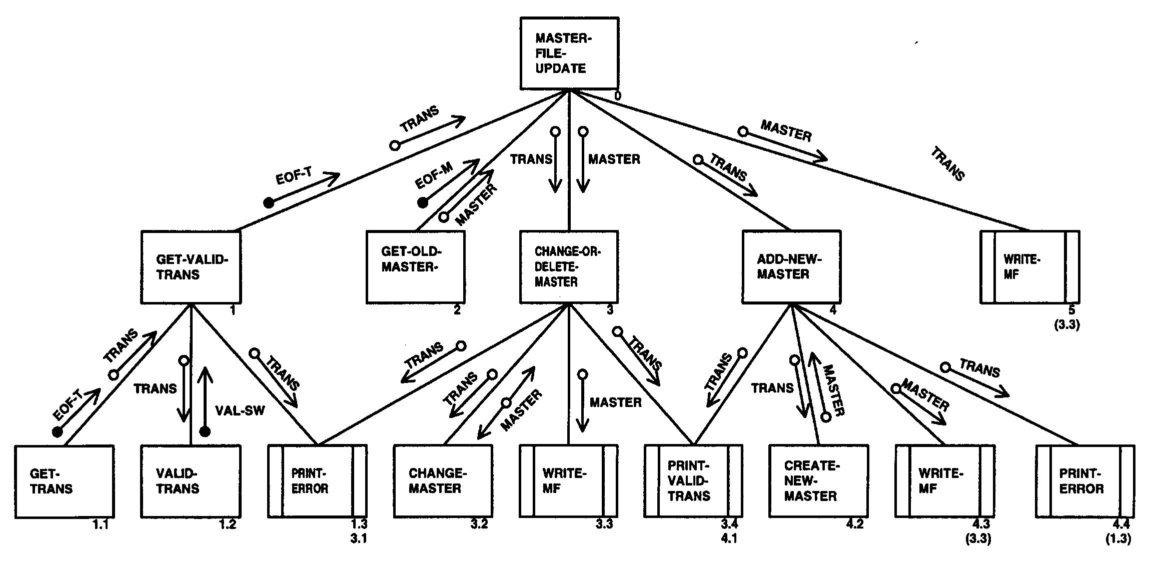
Please click here for the text description of the image.
| Parameter Table | ||
|---|---|---|
| No. | Input | Output |
| 1. | PURPOSELY LEFT BLANK | VALID-TRANS-REC, END-OF-VALID-TRANS-IND |
| 2. | VALID-TRANS-REC | MATCHED-TRANS-MASTER-REC, NO-MATCH-TRANS-IND |
| 3. | MATCHED-TRANS-MASTER-REC | UPDATED-MASTER-REC |
| 4. | UPDATED-MASTER-REC | PURPOSELY LEFT BLANK |
| 5. | TRANS-KEY | MASTER-REC, NO-MATCH-TRANS-IND |
| 6. | VALID-TRANS-REC, MASTER-REC | MATCHED-TRANS-MASTER-REC |
| 7. | VALID-TRANS-REC | PURPOSELY LEFT BLANK |
| 8. | MATCHED-TRANS-MASTER-REC | UPDATED-MASTER-REC |
| 9. | UPDATED-MASTER-REC | PURPOSELY LEFT BLANK |
| 10. | VALID-TRANS-REC | NO-MATCH-TRANS-REPORT-REC |
| 11. | NO-MATCH-TRANS-REPORT-REC | PURPOSELY LEFT BLANK |
| 12. | DEBIT-SECTION, MONEY-BALANCE, TRANS-DATA | DEBIT-SECTION, MONEY-BALANCE, LAST-POSTING-DATE |
| 13. | CREDIT-SECTION, MONEY-BALANCE, TRANS-DATA | CREDIT-SECTION, MONEY-BALANCE, LAST-POSTING-DATE |
| Acronym | Definition |
|---|---|
| GOF | Gang of Four |
| IEEE-SA | Institute of Electrical and Electronics Engineers Standards Association (IEEE-SA) |
| FISMA | Federal Information Security Modernization Act |
| FOIA | Freedom of Information Act |
| IMF | Individual Master File |
| SRS | Software Requirement Specification |
| SSDF | Secure Software Development Framework |
Terms/Definitions
| Terms | Definition |
|---|---|
| Algorithm | An algorithm is step-by-step procedure for solving a problem. |
| Architecture Description Languages | A language that provides syntax and semantics for defining a software architecture. The notation specification provides features for modeling a software system’s conceptual architecture. |
| Abstraction | Abstraction is a tool that enables a designer to consider a component at a abstract level without the concerns of the internal details of the implementation. |
| Inheritance | Inheritance is a mechanism that permits new classes to be created out of existing classes by extending and refining its capabilities. |
| Interface | Software interconnections that allow a device, program, or a person to interact. |
| Object Design | A design model is developed based on both the models developed in the system analysis phase, and the architecture designed in the system design phase. |
| Object Model | Displays the elements in a software application in terms of objects. |
| Refactor | A systematic process of improving code without creating new functionality. Refactoring can transform unorganized code into clean code and simple design. |
| Requirements Visualization Methodology | An iterative process of collaboration, design, and feedback. |
| Simulations | Simulations are models that imitate the proposed product or software solution. Simulations can be low, medium, or high in fidelity, but users are able to interact with the product. |